Toyota Yaris: Power Steering System / Power Steering Torque Sensor "A" Supply Voltage Circuit Voltage Above Threshold (C151A17)
DESCRIPTION
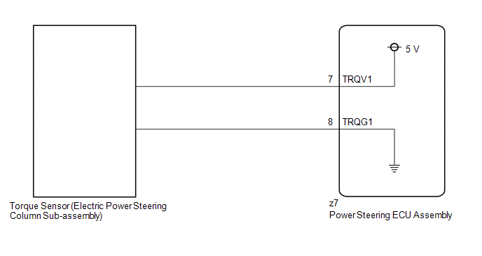
The power steering ECU assembly supplies a voltage of 5 V to the torque sensor (electric power steering column sub-assembly) and monitors the voltage value of the Hall IC inside the torque sensor (electric power steering column sub-assembly) which changes in response to changes in the magnetic flux density (steering torque) detected by the Hall IC, and calculates the assist torque.
While DTC C151A17 is detected, power assist is stopped or assist amount is limited due to fail-safe operation.
| DTC No. | Detection Item | DTC Detection Condition | Trouble Area | Warning Indicate | Return-to-normal Condition | Note |
|---|---|---|---|---|---|---|
| C151A17 | Power Steering Torque Sensor "A" Supply Voltage Circuit Voltage Above Threshold | TRQV1 voltage is 5.6 V or more |
| EPS warning light: Comes on | Ignition switch ON again | - |
WIRING DIAGRAM
CAUTION / NOTICE / HINT
NOTICE:
-
When the electric power steering column sub-assembly has been replaced, perform Power Steering ECU Initial Setting (assist map writing).
Click here

-
When the power steering ECU assembly has been replaced, perform Power Steering ECU Initial Setting (assist map writing).
Click here

PROCEDURE
| 1. | INSPECT TORQUE SENSOR (ELECTRIC POWER STEERING COLUMN SUB-ASSEMBLY) (CHECK FOR SHORT) |
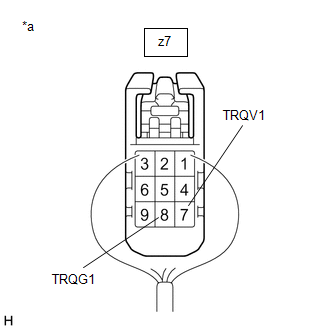
(a) Disconnect the z7 power steering ECU assembly connector.
(b) Measure the resistance according to the value(s) in the table below.
Standard Resistance:
| Tester Connection | Condition | Specified Condition |
|---|---|---|
| z7-7 (TRQV1) - Body ground | Always | 10 kΩ or higher |
| z7-7 (TRQV1) - z7-8 (TRQG1) | Always | 10 kΩ or higher |
| NG |
 | REPLACE ELECTRIC POWER STEERING COLUMN SUB-ASSEMBLY |
|

| 2. | INSPECT POWER STEERING ECU ASSEMBLY (POWER SOURCE OF TORQUE SENSOR) |
(a) Start the engine.
| (b) Measure the voltage according to the value(s) in the table below. Standard Voltage:
|
|
| OK |
 | REPLACE ELECTRIC POWER STEERING COLUMN SUB-ASSEMBLY |
| NG |
 | REPLACE POWER STEERING ECU ASSEMBLY |
 Power Steering Torque Sensor "A" Signal Compare Failure (C151162,C151187,C151262,C151287)
DESCRIPTION The power steering ECU assembly supplies a voltage of 5 V to the torque sensor (electric power steering column sub-assembly) and monitors the voltage value of the Hall IC inside the torque sensor (electric power steering column sub-assembly) which changes in response to changes in the magnetic flux density (steering torque) detected by the Hall IC, and calculates the assist torque...
 Power Steering Torque Sensor "B" Supply Voltage Circuit Voltage Above Threshold (C151B17)
DESCRIPTION The power steering ECU assembly supplies a voltage of 5 V to the torque sensor (electric power steering column sub-assembly) and monitors the voltage value of the Hall IC inside the torque sensor (electric power steering column sub-assembly) which changes in response to changes in the magnetic flux density (steering torque) detected by the Hall IC, and calculates the assist torque...
Other information:
Toyota Yaris XP210 (2020-2025) Reapir and Service Manual: Components
COMPONENTS ILLUSTRATION *1 BACK DOOR TRIM BOARD *2 BACK DOOR TRIM COVER ILLUSTRATION *1 BACK DOOR LOCK ASSEMBLY WITH COURTESY LIGHT SWITCH *2 DOOR PULL HANDLE *3 BACK DOOR OUTSIDE GARNISH SUB-ASSEMBLY *4 BACK DOOR OPENER SWITCH ASSEMBLY *5 NO...
Toyota Yaris XP210 (2020-2025) Reapir and Service Manual: IGR Diode Stuck Off (B235A9F)
DESCRIPTION This DTC is output when a diode failure between the IGP input and the IGR input in the power distribution box assembly is detected. DTC No. Detection Item DTC Detection Condition Trouble Area B235A9F IGR Diode Stuck Off At the time of IGP input state ON, an IGR input state continues OFF state for three consecutive trips...
Categories
- Manuals Home
- Toyota Yaris Owners Manual
- Toyota Yaris Service Manual
- Auto Lock/Unlock Function
- Fuel Gauge
- Removal
- New on site
- Most important about car
Keys

To use the auxiliary key, press the knob and pull out the auxiliary key from the smart key.
