Toyota Yaris: Parking Brake / Parking Brake Switch
Components
COMPONENTS
ILLUSTRATION
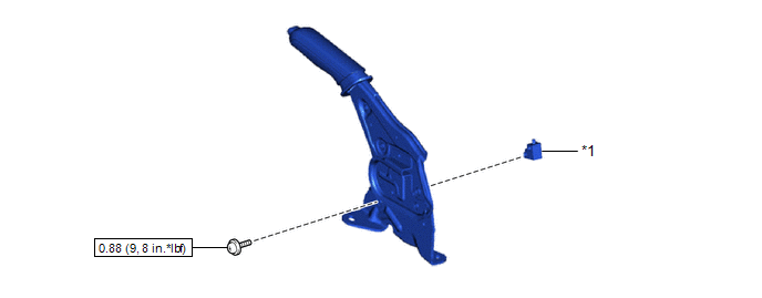
| *1 | PARKING BRAKE SWITCH ASSEMBLY | - | - |
 | N*m (kgf*cm, ft.*lbf): Specified torque | - | - |
Removal
REMOVAL
PROCEDURE
1. REMOVE REAR CONSOLE BOX ASSEMBLY
Click here

2. REMOVE PARKING BRAKE SWITCH ASSEMBLY
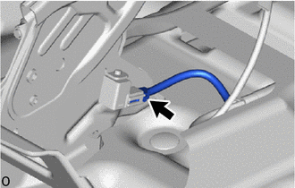
| (a) Disconnect the parking brake switch connector. |
|
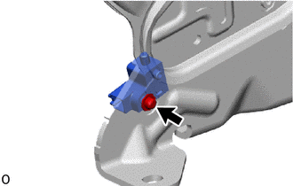
| (b) Remove the screw and parking brake switch assembly. |
|
Inspection
INSPECTION
PROCEDURE
1. INSPECT PARKING BRAKE SWITCH ASSEMBLY
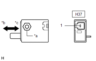
| (a) Measure the resistance between the connector terminal and the nut inside the parking brake switch assembly. Standard Resistance
If the result is not as specified, replace the parking brake switch assembly. |
|
Installation
INSTALLATION
PROCEDURE
1. INSTALL PARKING BRAKE SWITCH ASSEMBLY
(a) Install the parking brake switch assembly with the screw.
Torque:
0.88 N·m {9 kgf·cm, 8 in·lbf}
(b) Connect the parking brake switch connector.
2. INSTALL REAR CONSOLE BOX ASSEMBLY
Click here

 Parking Brake Lever
ComponentsCOMPONENTS ILLUSTRATION
*1 PARKING BRAKE CABLE ASSEMBLY *2 PARKING BRAKE LEVER SUB-ASSEMBLY *3 NO. 1 PARKING BRAKE CABLE ASSEMBLY *4 PARKING BRAKE SWITCH ASSEMBLY *5 NO...
 Parking Brake System
Problem Symptoms TablePROBLEM SYMPTOMS TABLE HINT: Use the table below to help determine the cause of problem symptoms. If multiple suspected areas are listed, the potential causes of the symptoms are listed in order of probability in the "Suspected Area" column of the table...
Other information:
Toyota Yaris XP210 (2020-2026) Reapir and Service Manual: Multi-axis Acceleration Sensor Module "A" Missing Calibration (C051D54,C121054)
DESCRIPTION The airbag sensor assembly has a built-in yaw rate and acceleration sensor and detects the vehicle condition. The skid control ECU (brake actuator assembly) receives signals from the yaw rate and acceleration sensor (airbag sensor assembly) via CAN communication...
Toyota Yaris XP210 (2020-2026) Reapir and Service Manual: After Engine Stops due to Stop and Start System, Engine does not Restart
DESCRIPTION This is the troubleshooting procedure for situations where the engine does not restart after having been stopped by the stop and start system. For information on stop and start control, refer to the system description. Click here CAUTION / NOTICE / HINT PRECAUTIONS WHEN THE ENGINE STOP AND START ECU AND THE STARTER ASSEMBLY ARE REPLACED NOTICE: When the engine stop and start ECU is replaced, it is necessary to read the number of starter operations before replacement and store this number in the new engine stop and start ECU after replacement, and to perform external backup boost converter (eco run vehicle converter assembly) existence learning...
Categories
- Manuals Home
- Toyota Yaris Owners Manual
- Toyota Yaris Service Manual
- Key Battery Replacement
- Engine Start Function When Key Battery is Dead
- To Set Speed
- New on site
- Most important about car
Front Seat Belt Pretensioners
The front seat belt pretensioners are designed to deploy in moderate or severe frontal, near frontal collisions.
In addition, the pretensioners operate when a side collision or a rollover accident is detected. The pretensioners operate differently depending on what types of air bags are equipped. For more details about the seat belt pretensioner operation, refer to the SRS Air Bag Deployment Criteria.