Toyota Yaris: Power Door Lock Control System / Only Back Door cannot be Opened
DESCRIPTION
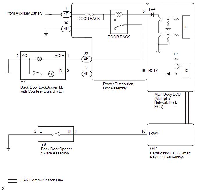
The main body ECU (multiplex network body ECU) receives signals from the back door opener switch assembly. Then, the main body ECU (multiplex network body ECU) activates the back door lock motor.
WIRING DIAGRAM
CAUTION / NOTICE / HINT
NOTICE:
- When using the GTS with the vehicle ignition switch off, connect the GTS to the DLC3 and turn a courtesy light switch on and off at intervals of 1.5 seconds or less until communication between the GTS and the vehicle begins. Then select Model Code "KEY REGIST" under manual mode and enter the following menus: Body Electrical / Smart Key. While using the GTS, periodically turn a courtesy light switch on and off at intervals of 1.5 seconds or less to maintain communication between the GTS and the vehicle.
- Inspect the fuses for circuits related to this system before performing the following procedure.
-
If the main body ECU (multiplex network body ECU) is replaced, refer to the Registration.
Click here

-
The power door lock control system uses the CAN communication system. Inspect the communication function by following How to Proceed with Troubleshooting. Troubleshoot the power door lock control system after confirming that the communication systems are functioning properly.
Click here

PROCEDURE
| 1. | PERFORM ACTIVE TEST USING GTS (Trunk Lid / Back Door Open) |
(a) Perform the Active Test according to the display on the GTS.
Body Electrical > Main Body > Active Test| Tester Display |
|---|
| Trunk Lid / Back Door Open |
OK:
The back door lock assembly with courtesy light switch unlatches when ON is selected.
Body Electrical > Main Body > Active Test| Tester Display | Measurement Item | Control Range | Diagnostic Note |
|---|---|---|---|
| Trunk Lid / Back Door Open | Back door lock motor | OFF/ON | - |
| OK |
 | GO TO ENTRY AND START SYSTEM (for Entry Function) |
|

| 2. | INSPECT BACK DOOR LOCK ASSEMBLY WITH COURTESY LIGHT SWITCH |
Click here

| NG |
 | REPLACE BACK DOOR LOCK ASSEMBLY WITH COURTESY LIGHT SWITCH |
|

| 3. | CHECK HARNESS AND CONNECTOR (BACK DOOR LOCK ASSEMBLY WITH COURTESY LIGHT SWITCH - POWER DISTRIBUTION BOX ASSEMBLY AND BODY GROUND) |
(a) Disconnect the Y7 back door lock assembly with courtesy light switch connector.
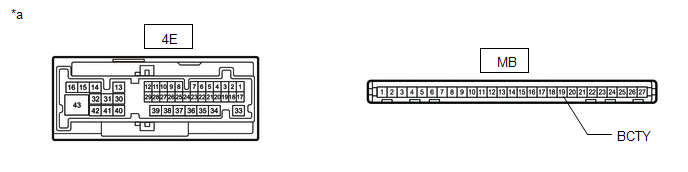
(b) Disconnect the 4E power distribution box assembly connector.
(c) Measure the resistance according to the value(s) in the table below.
Standard Resistance:
| Tester Connection | Condition | Specified Condition |
|---|---|---|
| Y7-1 (ACT+) - 4E-39 | Always | Below 1 Ω |
| Y7-3 (D+) - 4E-2 | Always | Below 1 Ω |
| Y7-2 (ACT-) - Body ground | Always | Below 1 Ω |
| Y7-1 (ACT+) or 4E-39 - Body ground | Always | 10 kΩ or higher |
| Y7-3 (D+) or 4E-4 - Body ground | Always | 10 kΩ or higher |
| NG |
 | REPAIR OR REPLACE HARNESS OR CONNECTOR |
|

| 4. | INSPECT POWER DISTRIBUTION BOX ASSEMBLY |
(a) Remove the power distribution box assembly.
Click here

(b) Remove the main body ECU (multiplex network body ECU) from the power distribution box assembly.
Click here

(c) Measure the resistance according to the value(s) in the table below.
| *a | Component without harness connected (Power Distribution Box Assembly) | - | - |
Standard Resistance:
| Tester Connection | Condition | Specified Condition |
|---|---|---|
| MB-19 (BCTY) - 4E-2 | Always | Below 1 Ω |
| NG |
 | REPLACE POWER DISTRIBUTION BOX ASSEMBLY |
|

| 5. | CHECK HARNESS AND CONNECTOR (POWER DISTRIBUTION BOX ASSEMBLY - AUXILIARY BATTERY AND BODY GROUND) |
(a) Disconnect the power distribution box assembly connectors.
| *a | Component without harness connected (Power Distribution Box Assembly) | - | - |
(b) Measure the voltage according to the value(s) in the table below.
Standard Voltage:
| Tester Connection | Switch Condition | Specified Condition |
|---|---|---|
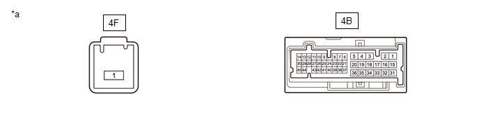
| 4F-1 - Body ground | Ignition switch off | 11 to 14 V |
(c) Measure the resistance according to the value(s) in the table below.
Standard Resistance:
| Tester Connection | Condition | Specified Condition |
|---|---|---|
| 4B-36 - Body ground | Always | Below 1 Ω |
| NG |
 | REPAIR OR REPLACE HARNESS OR CONNECTOR |
|

| 6. | CHECK POWER DISTRIBUTION BOX ASSEMBLY (DOOR BACK RELAY) |
(a) Remove the power distribution box assembly.
Click here

(b) Remove the main body ECU (multiplex network body ECU) from the power distribution box assembly.
Click here

(c) Measure the resistance according to the value(s) in the table below.
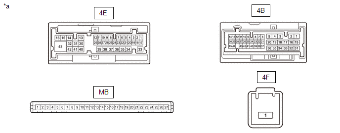
| *a | Front view of wire harness connector (to Power Distribution Box Assembly) | - | - |
Standard Resistance:
| Tester Connection | Condition | Specified Condition |
|---|---|---|
| 4B-36 - 4E-39 | Auxiliary battery voltage applied between 4F-1 and MB-5 (TR+) | 10 kΩ or higher |
| 4B-36 - 4E-39 | Auxiliary battery voltage not applied between 4F-1 and MB-5 (TR+) | Below 1 Ω |
(d) Measure the voltage according to the value(s) in the table below.
Standard Voltage:
| Tester Connection | Condition | Specified Condition |
|---|---|---|
| 4E-39 - Auxiliary battery negative (-) terminal | Auxiliary battery voltage applied between 4F-1 and MB-5 (TR+) | 11 to 14 V |
| OK |
 | REPLACE MAIN BODY ECU (MULTIPLEX NETWORK BODY ECU) |
| NG |
 | REPLACE POWER DISTRIBUTION BOX ASSEMBLY |
 All Doors LOCK/UNLOCK Functions do not Operate Via Master Switch
DESCRIPTION The main body ECU (multiplex network body ECU) receives switch signals from the multiplex network master switch assembly via LIN communication system...
 Wireless Door Lock Buzzer
ComponentsCOMPONENTS ILLUSTRATION
*1 WIRELESS DOOR LOCK BUZZER - - RemovalREMOVAL PROCEDURE 1. REMOVE FRONT FENDER LINER LH HINT: Use the same procedure as for front fender liner RH...
Other information:
Toyota Yaris XP210 (2020-2026) Reapir and Service Manual: Oil And Oil Filter
ComponentsCOMPONENTS ILLUSTRATION *1 OIL FILTER SUB-ASSEMBLY *2 OIL FILLER CAP SUB-ASSEMBLY *3 GASKET *4 OIL PAN DRAIN PLUG *5 REAR ENGINE UNDER COVER RH - - Tightening torque for "Major areas involving basic vehicle performance such as moving/turning/stopping" : N*m (kgf*cm, ft...
Toyota Yaris XP210 (2020-2026) Reapir and Service Manual: Ambient Temperature Display System
DESCRIPTION The thermistor assembly is installed in front of the cooler condenser assembly to detect the ambient temperature, which is used to control the automatic air conditioning system. The thermistor assembly detects fluctuations in the ambient temperature and sends it as a signal to the combination meter assembly...
Categories
- Manuals Home
- Toyota Yaris Owners Manual
- Toyota Yaris Service Manual
- Fuel Gauge
- To Set Speed
- Removal
- New on site
- Most important about car
Fuel Gauge
The fuel gauge shows approximately how much fuel is remaining in the tank when the ignition is switched ON. We recommend keeping the tank over 1/4 full.
