Toyota Yaris: Front Drive Shaft Assembly / Reassembly
REASSEMBLY
CAUTION / NOTICE / HINT
NOTICE:
- When using a vise, place aluminum plates between the part and vise.
- When using a vise, do not overtighten it.
HINT:
- Use the same procedure for the RH side and LH side.
- The following procedure is for the LH side.
PROCEDURE
1. INSTALL FRONT DRIVE SHAFT BEARING (for RH Side)
| (a) Using SST, a steel plate and a press, press in the front drive inboard joint assembly RH until a new front drive shaft bearing contacts the edge of the front drive inboard joint assembly RH. SST: 09710-30012 09710-04061 NOTICE:
|
|
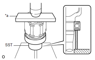
| (b) Using a snap ring expander, install a new snap ring. NOTICE: The snap ring should be installed completely. |
|
2. INSTALL FRONT DRIVE SHAFT DUST COVER RH (for RH Side)
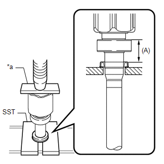
| (a) Using SST, a steel plate and a press, install a new front drive shaft dust cover RH to the front drive inboard joint assembly RH until the distance from the tip of the front drive inboard joint assembly RH to the front drive shaft dust cover RH reaches the specification as shown in the illustration. SST: 09527-10011 Standard Distance (A): 58.8 to 59.4 mm (2.31 to 2.34 in.) NOTICE:
|
|
3. INSTALL FRONT AXLE OUTBOARD JOINT BOOT
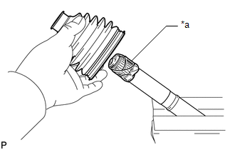
| (a) Wrap the splines of the front drive outboard joint shaft assembly with protective tape to prevent the boot from being damaged. |
|
(b) Install new parts to the front drive outboard joint shaft assembly in the following order:
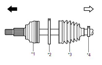
| *1 | Front Drive Outboard Joint Shaft Assembly |
| *2 | Front No. 2 Axle Outboard Joint Boot Clamp |
| *3 | Front Axle Outboard Joint Boot |
| *4 | Front Axle Outboard Joint Boot Clamp |
 | Outboard Joint Side |
 | Inboard Joint Side |
(1) Front No. 2 axle outboard joint boot clamp
(2) Front axle outboard joint boot
(3) Front axle outboard joint boot clamp
(c) Pack the joint portion of the front drive outboard joint shaft assembly and front axle outboard joint boot with grease.
Standard Grease Capacity:
105 to 115 g (3.70 to 4.06 oz.)
(d) Install the front axle outboard joint boot to the front drive outboard joint shaft assembly groove.
NOTICE:
- Do not allow grease to adhere to the boot clamp track of the outboard joint boot.
- Keep the inside of the outboard joint boot free of foreign matter.
4. INSTALL FRONT NO. 2 AXLE OUTBOARD JOINT BOOT CLAMP
(a) Install the front No. 2 axle outboard joint boot clamp to the front axle outboard joint boot.
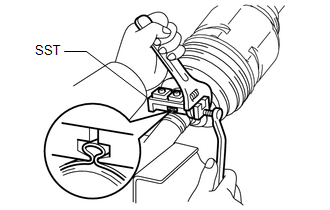
| (b) Place SST onto the front No. 2 axle outboard joint boot clamp, press it against the boot and slightly tighten SST. SST: 09521-24010 |
|
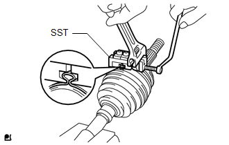
(c) Tighten SST so that the front No. 2 axle outboard joint boot clamp is pinched.
NOTICE:
Do not overtighten SST.
(d) Remove SST.
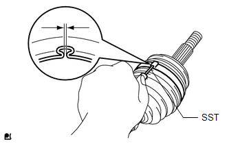
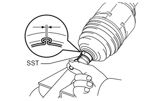
| (e) Using SST, measure the clearance of the front No. 2 axle outboard joint boot clamp. SST: 09240-00021 Standard Clearance: 0.5 to 1.5 mm (0.0197 to 0.0591 in.) If the clearance is not as specified, retighten SST. |
|
5. INSTALL FRONT AXLE OUTBOARD JOINT BOOT CLAMP
(a) Install the front axle outboard joint boot clamp to the front axle outboard joint boot.
| (b) Place SST onto the front axle outboard joint boot clamp, press it against the boot and slightly tighten SST. SST: 09521-24010 |
|
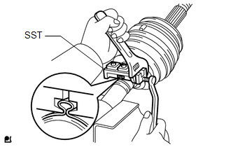
(c) Tighten SST so that the front axle outboard joint boot clamp is pinched.
NOTICE:
Do not overtighten SST.
(d) Remove SST.
| (e) Using SST, measure the clearance of the front axle outboard joint boot clamp. SST: 09240-00021 Standard Clearance: 0.5 to 1.5 mm (0.0197 to 0.0591 in.) If the clearance is not as specified, retighten SST. |
|
6. INSTALL FRONT DRIVE INBOARD JOINT ASSEMBLY
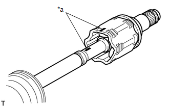
(a) Install new parts to the front drive outboard joint shaft assembly in the following order:

| *1 | Front Axle Inboard Joint Boot Clamp |
| *2 | Front Axle Inboard Joint Boot |
| *3 | Front No. 2 Axle Inboard Joint Boot Clamp |
| *a | Protective Tape |
 | Outboard Joint Side |
 | Inboard Joint Side |
(1) Front axle inboard joint boot clamp
(2) Front axle inboard joint boot
(3) Front No. 2 axle inboard joint boot clamp
(b) Remove the protective tape.
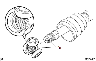
| (c) Align the matchmarks and install the tripod joint to the front drive outboard joint shaft assembly. NOTICE: Face the serrated side of the tripod joint outward and install it to the outboard joint end. |
|
(d) Using a brass bar and a hammer, install the tripod joint to the front drive outboard joint shaft assembly.
NOTICE:
- Do not tap the rollers.
- Keep the tripod joint free of foreign matter.
- Be sure to install the tripod joint in the correct direction.
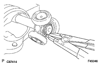
| (e) Using a snap ring expander, install a new shaft snap ring to the front drive outboard joint shaft assembly. |
|
(f) Pack the front drive inboard joint assembly and front axle inboard joint boot with grease.
Standard Grease Capacity:
168 to 178 g (5.93 to 6.28 oz.)
| (g) Align the matchmarks and install the front drive inboard joint assembly to the front drive outboard joint shaft assembly. |
|
7. INSTALL FRONT AXLE INBOARD JOINT BOOT
(a) Install the front axle inboard joint boot to the front drive inboard joint assembly.
NOTICE:
- Keep the grooves free of grease.
- Keep the inside of the front axle inboard joint boot free of foreign matter.
| (b) Check whether the dimension (A) of each drive shaft is within specification. Dimension (A):
|
|
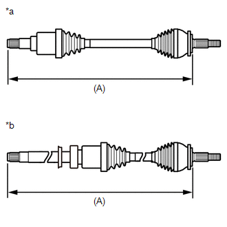
(c) While keeping dimension (A) within the specified length, equalize the pressure within the inboard joint with atmospheric pressure by slightly lifting the front axle inboard joint boot from the front drive inboard joint assembly.
8. INSTALL FRONT AXLE INBOARD JOINT BOOT CLAMP
(a) Install the front axle inboard joint boot clamp to the front axle inboard joint boot.
| (b) Place SST onto the front axle inboard joint boot clamp, press it against the boot and slightly tighten SST. SST: 09521-24010 |
|
(c) Tighten SST so that the front axle inboard joint boot clamp is pinched.
NOTICE:
Do not overtighten SST.
(d) Remove SST.
| (e) Using SST, measure the clearance of the front axle inboard joint boot clamp. SST: 09240-00021 Standard Clearance: 0.5 to 1.5 mm (0.0197 to 0.0591 in.) If the clearance is not as specified, retighten SST. |
|
9. INSTALL FRONT NO. 2 AXLE INBOARD JOINT BOOT CLAMP
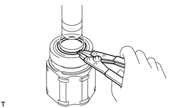
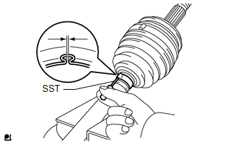
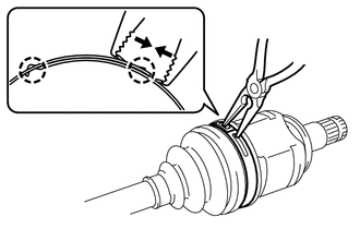
| (a) Using needle-nose pliers, engage the claws and install the front No. 2 axle inboard joint boot clamp as shown in the illustration. NOTICE:
|
|
10. INSPECT FRONT DRIVE SHAFT ASSEMBLY
Click here

 Inspection
INSPECTION PROCEDURE 1. INSPECT FRONT DRIVE SHAFT ASSEMBLY (a) Check that there is no excessive play in the radial direction of the outboard joint.
(b) Check that the inboard joint slides smoothly in the thrust direction...
 Installation
INSTALLATION CAUTION / NOTICE / HINT HINT:
Use the same procedure for the RH side and LH side.
The following procedure is for the LH side.
PROCEDURE 1...
Other information:
Toyota Yaris XP210 (2020-2026) Reapir and Service Manual: Removal
REMOVAL PROCEDURE 1. REMOVE CENTER STOP LIGHT COVER (a) Disengage the claws to remove the center stop light cover. (b) Disengage the claws and disconnect the connector. 2. REMOVE REAR SPOILER HOLE COVER (a) Remove the 4 rear spoiler hole covers...
Toyota Yaris XP210 (2020-2026) Reapir and Service Manual: Installation
INSTALLATION PROCEDURE 1. INSTALL SEMICONDUCTOR POWER INTEGRATION ECU NOTICE: Make sure the connector terminal is free from oil and grease. Do not subject the semiconductor power integration ECU to any impact. Do not use a semiconductor power integration ECU that has been dropped...
Categories
- Manuals Home
- Toyota Yaris Owners Manual
- Toyota Yaris Service Manual
- To Set Speed
- Engine Start Function When Key Battery is Dead
- Auto Lock/Unlock Function
- New on site
- Most important about car
Refueling
Before refueling, close all the doors, windows, and the liftgate/trunk lid, and switch the ignition OFF.
To open the fuel-filler lid, pull the remote fuel-filler lid release.
