Toyota Yaris: Radiator / Removal
REMOVAL
CAUTION / NOTICE / HINT
HINT:
When the cable is disconnected / reconnected to the auxiliary battery terminal, systems temporarily stop operating. However, each system has a function that completes learning the first time the system is used.
-
Learning completes when vehicle is driven
Effect/Inoperative Function When Necessary Procedures are not Performed
Necessary Procedures
Link
Lane tracing assist system
Drive the vehicle straight ahead at 35 km/h (22 mph) or more for 5 second or more.

Pre-collision system
Stop and start system
Drive the vehicle until stop and start control is permitted (approximately 5 to 60 minutes)

-
Learning completes when vehicle is operated normally
Effect/Inoperative Function When Necessary Procedures are not Performed
Necessary Procedures
Link
Power door lock control system
- Back door opener
Perform door unlock operation with door control switch or electrical key transmitter sub-assembly switch.

Air conditioning system
After the ignition switch is turned to ON, the servo motor standard position is recognized.
-
PROCEDURE
1. PRECAUTION
NOTICE:
After the ignition switch is turned off, the radio and display receiver assembly records various types of memory and settings. As a result, after turning the ignition switch off, make sure to wait at least 120 seconds before disconnecting the cable from the negative (-) auxiliary battery terminal.
2. DISCONNECT CABLE FROM NEGATIVE AUXILIARY BATTERY TERMINAL
Click here

3. REMOVE NO. 1 ENGINE UNDER COVER ASSEMBLY
Click here

4. DRAIN ENGINE COOLANT
Click here

5. REMOVE HEADLIGHT ASSEMBLY LH
Click here

6. REMOVE HEADLIGHT ASSEMBLY RH
HINT:
Use the same procedure as for the LH side.
7. REMOVE NO. 3 AIR CLEANER INLET
| (a) Disengage the 2 claws to remove the No. 3 air cleaner inlet from the vehicle. |
|
8. REMOVE NO. 1 AIR CLEANER INLET
| (a) Remove the 2 clips and No. 1 air cleaner inlet from the vehicle. |
|
9. REMOVE RADIATOR UPPER AIR GUIDE PLATE
Click here

10. REMOVE FRONT BUMPER ENERGY ABSORBER
Click here

11. REMOVE COOL AIR INTAKE DUCT
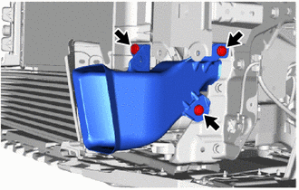
| (a) Remove the 3 clips and cool air intake duct from the vehicle. |
|
12. REMOVE FRONT BUMPER REINFORCEMENT
Click here

13. REMOVE HOOD LOCK ASSEMBLY
Click here

14. REMOVE UPPER RADIATOR SUPPORT SUB-ASSEMBLY
(a) Disconnect the 2 airbag connectors.
NOTICE:
When disconnecting any airbag connector, take care not to damage the airbag wire harness.
HINT:
Refer to How to Connect or Disconnect Airbag Connector:
Click here

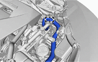
| (b) Disconnect the hood lock control cable assembly from the upper radiator support sub-assembly. |
|
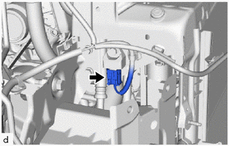
| (c) Disconnect the airbag connector. |
|
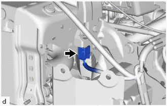
| (d) Disconnect the airbag connector. |
|
| (e) Disconnect the horn connector. |
|
(f) Disengage the 3 clamps.
| (g) Disengage the clamp. |
|
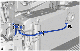
| (h) Disengage the 3 clamps to disconnect the wire harness from the upper radiator support sub-assembly. |
|
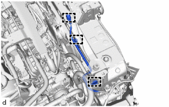
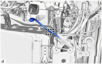
| (i) Disengage the clamps to disconnect the No. 3 water by-pass hose from the upper radiator support sub-assembly. |
|
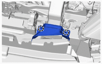
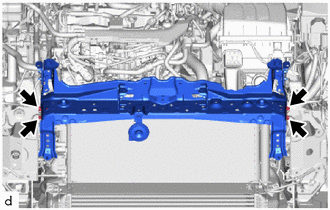
| (j) Remove the 4 bolts and upper radiator support sub-assembly from the front side member bracket sub-assembly. |
|
15. REMOVE FRONT RADIATOR SIDE AIR GUIDE PLATE LH
Click here

16. REMOVE FRONT RADIATOR SIDE AIR GUIDE PLATE RH
Click here

17. REMOVE NO. 1 RADIATOR AIR GUIDE LH
| (a) Disengage the 2 clamps and disconnect the wire harness. |
|
(b) Disengage the claw and 2 guides to remove the No. 1 radiator air guide LH.
18. REMOVE NO. 1 RADIATOR AIR GUIDE RH
| (a) Disengage the claw and 2 guides to remove the No. 1 radiator air guide LH. |
|
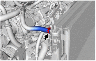
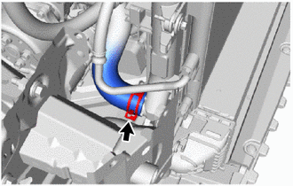
19. DISCONNECT WATER BY-PASS HOSE
| (a) Disengage the clamp. |
|
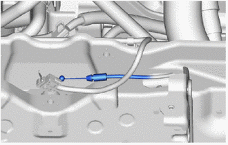
(b) Slide the clip and disconnect the water by-pass hose from the radiator assembly.
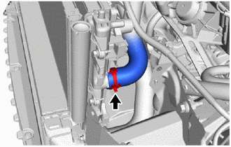
20. DISCONNECT NO. 3 WATER BY-PASS HOSE
| (a) Slide the clip and disconnect the No. 3 water by-pass hose from the radiator assembly. |
|
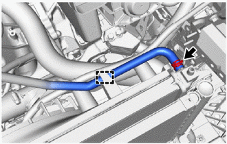
21. DISCONNECT NO. 1 RADIATOR HOSE
| (a) Slide the clip and disconnect the No. 1 radiator hose from the radiator assembly. |
|
22. DISCONNECT NO. 2 RADIATOR HOSE
| (a) Slide the clip and disconnect the No. 2 radiator hose from the radiator assembly. |
|
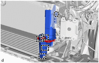
23. SEPARATE COOLER CONDENSER ASSEMBLY
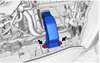
| (a) Remove the 3 bolts. |
|
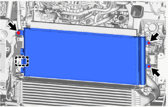
(b) Disengage the guide to separate the cooler condenser assembly from the radiator assembly.
NOTICE:
Do not damage the cooler condenser assembly or radiator assembly when removing the cooler condenser assembly.
24. DISCONNECT NO. 4 AIR HOSE
Click here

25. DISCONNECT NO. 3 AIR HOSE
Click here

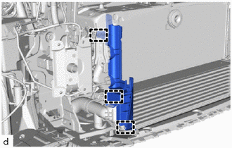
26. REMOVE INTERCOOLER ASSEMBLY
Click here

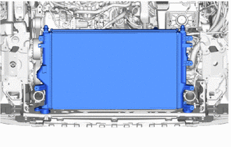
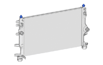
27. REMOVE RADIATOR ASSEMBLY
| (a) Remove the radiator assembly together with the fan shroud from the vehicle body. NOTICE: Do not apply excessive force to the cooler condenser assembly or pipe when removing the radiator assembly with the fan shroud. |
|
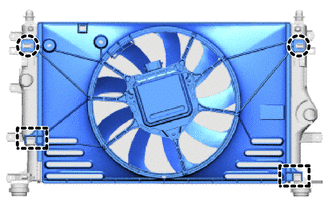
| (b) Disengage the 2 claws and 2 guides to remove the fan shroud from the radiator assembly. NOTICE: Do not damage the radiator assembly when removing the fan shroud. |
|
28. REMOVE RADIATOR SUPPORT CUSHION
| (a) Remove the 2 radiator support cushions from the radiator assembly. |
|
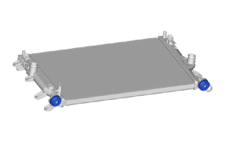
29. REMOVE LOWER RADIATOR SUPPORT
| (a) Remove the 2 lower radiator supports from the radiator assembly. |
|
30. REMOVE RADIATOR DRAIN COCK PLUG
| (a) Remove the radiator drain cock plug. |
|
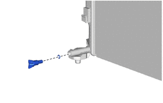
(b) Remove the O-ring from the radiator drain cock plug.
 On-vehicle Inspection
ON-VEHICLE INSPECTION PROCEDURE 1. INSPECT RESERVE TANK CAP CAUTION: Do not remove the reserve tank cap and air release valve while the engine and radiator assembly are still hot...
 Installation
INSTALLATION PROCEDURE 1. INSTALL RADIATOR DRAIN COCK PLUG (a) Install the O-ring to the radiator drain cock plug. NOTICE: Replace the O-ring if it is damaged...
Other information:
Toyota Yaris XP210 (2020-2026) Owner's Manual: Cleaning the Floor Mats
Rubber floor mats should be cleaned with mild soap and water only. After removing the floor mats for cleaning, always reinstall them securely. WARNING Do not use rubber cleaners, such as tire cleaner or tire shine, when cleaning rubber floor mats Cleaning the rubber floor mats with rubber cleaning products makes the floor mats slippery...
Toyota Yaris XP210 (2020-2026) Owner's Manual: Plastic Part Maintenance
When cleaning the plastic lenses of the lights, do not use gasoline, kerosene, rectified spirit, paint, thinner, highly acidic detergents, or strongly alkaline detergents. Otherwise, these chemical agents can discolor or damage the surfaces resulting in a significant loss in functionality...
Categories
- Manuals Home
- Toyota Yaris Owners Manual
- Toyota Yaris Service Manual
- How to use USB mode
- G16e-gts (engine Mechanical)
- Adjustment
- New on site
- Most important about car
Key Suspend Function
If a key is left in the vehicle, the functions of the key left in the vehicle are temporarily suspended to prevent theft of the vehicle.
To restore the functions, press the unlock button on the functions-suspended key in the vehicle.