Toyota Yaris: Radiator / On-vehicle Inspection
ON-VEHICLE INSPECTION
PROCEDURE
1. INSPECT RESERVE TANK CAP
CAUTION:
Do not remove the reserve tank cap and air release valve while the engine and radiator assembly are still hot. Pressurized, hot engine coolant and steam may be released and cause serious burns.
(a) Measure the valve opening pressure.
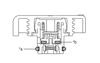
| *a | O-ring |
| *b | Rubber Packing |
(1) If there are water stains or foreign matter on the O-ring, clean it with water and finger scouring.
(2) Check that the O-ring is not deformed, cracked or swollen.
(3) Apply engine coolant to the O-ring and rubber packing before using a radiator cap tester.
(4) Install the radiator cap tester to the reserve tank cap.
| (5) When using the radiator cap tester, tilt it upwards 30° or more. |
|
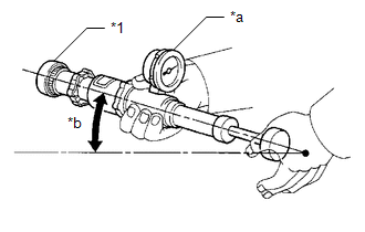
(6) Pump the radiator cap tester several times, and check the maximum pressure.
Pump Speed:
1 pump per second
| Item | Specified Condition |
|---|---|
| Standard pressure (for brand-new reserve tank cap) | 93 to 123 kPa (0.9 to 1.3 kgf/cm2, 13.5 to 18.0 psi) |
| Minimum pressure (for used reserve tank cap) | 79 kPa (0.8 kgf/cm2, 11.5 psi) |
HINT:
Even if the reserve tank cap cannot maintain the maximum pressure, it is not a defect.
If the maximum pressure is less than the minimum pressure, replace the reserve tank cap.
(7) Remove the radiator cap tester from the reserve tank cap.
 Components
COMPONENTS ILLUSTRATION
*1 FRONT BUMPER ENERGY ABSORBER *2 FRONT BUMPER REINFORCEMENT *3 RADIATOR UPPER AIR GUIDE PLATE *4 NO. 3 AIR CLEANER INLET *5 NO...
 Removal
REMOVAL CAUTION / NOTICE / HINT HINT: When the cable is disconnected / reconnected to the auxiliary battery terminal, systems temporarily stop operating...
Other information:
Toyota Yaris XP210 (2020-2026) Owner's Manual: Front Passenger Air Bag
The front passenger air bag is mounted in the front passenger dashboard. The inflation mechanism for the front passenger air bag is the same as the driver’s air bag, as mentioned above. For more details about air bag deployment, refer to “SRS Air Bag Deployment Criteria” In addition, the front passenger air bag is designed to only deploy in accordance with the total seated weight on the front passenger seat...
Toyota Yaris XP210 (2020-2026) Reapir and Service Manual: Throttle/Pedal Position Sensor "A" Minimum Stop Performance (P210900)
DESCRIPTION The idle speed is controlled by the Electronic Throttle Control System (ETCS). The ETCS is comprised of a throttle actuator, which operates the throttle valve, and a throttle position sensor, which detects the opening amount of the throttle valve...
Categories
- Manuals Home
- Toyota Yaris Owners Manual
- Toyota Yaris Service Manual
- Engine Start Function When Key Battery is Dead
- Immobilizer System
- Auto Lock/Unlock Function
- New on site
- Most important about car
Refueling
Before refueling, close all the doors, windows, and the liftgate/trunk lid, and switch the ignition OFF.
To open the fuel-filler lid, pull the remote fuel-filler lid release.
