Toyota Yaris: Lighting System / Light Sensor Circuit Malfunction (B124400)
DESCRIPTION
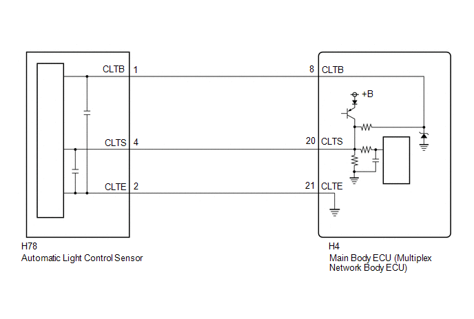
The automatic light control sensor detects ambient light. The sensor creates an electrical signal based on the amount of light detected, and sends the signal to the main body ECU (multiplex network body ECU). The main body ECU (multiplex network body ECU) turns on or off the headlights and taillights according to the signal.
| DTC No. | Detection Item | DTC Detection Condition | Trouble Area |
|---|---|---|---|
| B124400 | Light Sensor Circuit Malfunction |
|
|
WIRING DIAGRAM
CAUTION / NOTICE / HINT
NOTICE:
Before replacing the main body ECU (multiplex network body ECU), refer to Registration.
Click here
.gif)
PROCEDURE
| 1. | CLEAR DTC |
(a) Clear the DTCs.
Body Electrical > Main Body > Clear DTCs
|
.gif)
| 2. | CHECK FOR DTC |
(a) Turn the ignition switch to ON.
(b) Wait 10 seconds or more.
(c) Turn the GTS on.
(d) Enter the following menus: Body Electrical / Main Body / Trouble Codes.
(e) Check for DTCs.
Body Electrical > Main Body > Trouble Codes| Result | Proceed to |
|---|---|
| B124400 is output | A |
| B124400 is not output | B |
| B |
.gif) | USE SIMULATION METHOD TO CHECK |
|
| 3. | READ VALUE USING GTS |
(a) According to the display on the GTS, read the Data List and check that the value of Light Sensor Illuminance changes while performing the following:
(1) Cover the automatic light control sensor with an opaque object.
(2) Slowly move the opaque object to uncover and then cover the automatic light control sensor.
Body Electrical > Main Body > Data List| Tester Display | Measurement Item | Range | Normal Condition | Diagnostic Note |
|---|---|---|---|---|
| Light Sensor Illuminance | Light control sensor illuminance | 0 to 8191 lx or Sensor Fail | Value is output according to ambient light level | The displayed value is "0" when no light is detected. |
| Tester Display |
|---|
| Light Sensor Illuminance |
OK:
The value changes according to the amount the automatic light control sensor is covered.
| OK |
| REPLACE MAIN BODY ECU (MULTIPLEX NETWORK BODY ECU) |
|
| 4. | CHECK HARNESS AND CONNECTOR (AUTOMATIC LIGHT CONTROL SENSOR - MAIN BODY ECU (MULTIPLEX NETWORK BODY ECU)) |
(a) Disconnect the H78 automatic light control sensor connector.
(b) Disconnect the H4 main body ECU (multiplex network body ECU) connector.
(c) Measure the resistance according to the value(s) in the table below.
Standard Resistance:
| Tester Connection | Condition | Specified Condition |
|---|---|---|
| H78-1 (CLTB) - H4-8 (CLTB) | Always | Below 1 Ω |
| H78-4 (CLTS) - H4-20 (CLTS) | Always | Below 1 Ω |
| H78-2 (CLTE) - H4-21 (CLTE) | Always | Below 1 Ω |
| H78-1 (CLTB) or H4-8 (CLTB) - Body ground | Always | 10 kΩ or higher |
| H78-4 (CLTS) or H4-20 (CLTS) - Body ground | Always | 10 kΩ or higher |
| H78-2 (CLTE) or H4-21 (CLTE) - Body ground | Always | 10 kΩ or higher |
| NG |
| REPAIR OR REPLACE HARNESS OR CONNECTOR |
|
| 5. | INSPECT MAIN BODY ECU (MULTIPLEX NETWORK BODY ECU) |
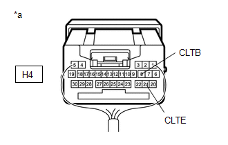
| *a | Component with harness connected (Main Body ECU (Multiplex Network Body ECU)) |
(a) Connect the H4 main body ECU (multiplex network body ECU) connector.
(b) Measure the voltage according to the value(s) in the table below.
Standard Voltage:
| Tester Connection | Switch Condition | Specified Condition |
|---|---|---|
| H4-8 (CLTB) - H4-21 (CLTE) | Ignition switch off | Below 1 V |
| H4-8 (CLTB) - H4-21 (CLTE) | Ignition switch ON | 11 to 14 V |
| NG |
| REPLACE MAIN BODY ECU (MULTIPLEX NETWORK BODY ECU) |
|
| 6. | INSPECT AUTOMATIC LIGHT CONTROL SENSOR |
Click here
| OK |
| REPLACE MAIN BODY ECU (MULTIPLEX NETWORK BODY ECU) |
| NG |
| REPLACE AUTOMATIC LIGHT CONTROL SENSOR |
 Vehicle Control History
VEHICLE CONTROL HISTORY CHECK VEHICLE CONTROL HISTORY HINT:
The vehicle control history data stores the history of the reject function and system protection operations...
 Headlight LH Circuit (B243900,B243A00)
DESCRIPTION The light control LED ECU supplies internally boosted voltage to the light control LED ECU LH so that the current supplied to the LED is always maintained at a constant value...
Other information:
Toyota Yaris XP210 (2020-2026) Reapir and Service Manual: Components
C..
Toyota Yaris XP210 (2020-2026) Reapir and Service Manual: Outer Rear View Mirror Cover
ComponentsCOMPONENTS ILLUSTRATION *1 OUTER MIRROR *2 OUTER MIRROR COVER RemovalREMOVAL CAUTION / NOTICE / HINT HINT: Use the same procedure for the RH side and LH side. The following procedure is for the LH side. PROCEDURE 1. REMOVE OUTER MIRROR Click here 2...
Categories
- Manuals Home
- Toyota Yaris Owners Manual
- Toyota Yaris Service Manual
- Battery Monitor Module General Electrical Failure (P058A01)
- How to use USB mode
- Removal
- New on site
- Most important about car
Key Suspend Function
If a key is left in the vehicle, the functions of the key left in the vehicle are temporarily suspended to prevent theft of the vehicle.
To restore the functions, press the unlock button on the functions-suspended key in the vehicle.