
Toyota Yaris: Fuel Main Valve / Installation
INSTALLATION
PROCEDURE
1. INSTALL FUEL MAIN VALVE ASSEMBLY
(a) Apply gasoline to a new O-ring.
| (b) Install the spacer and O-ring to the fuel main valve assembly. |
|
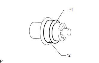
(c) Install the fuel main valve assembly to the fuel suction with pump and gauge tube assembly.
NOTICE:
Make sure that the O-ring is not cut or pinched during installation.
(d) Attach the 3 claws and install the No. 3 fuel suction support to the fuel suction with pump and gauge tube assembly.
(e) Attach the 4 claws and connect the sub-assembly support to the fuel suction with pump and gauge tube assembly.
(f) Apply gasoline to a new O-ring.
| (g) Install the O-ring to the fuel suction tube. |
|
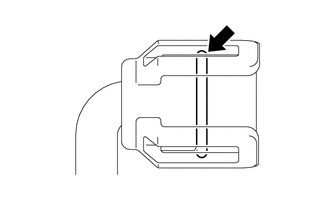
(h) Attach the 2 claws and 2 clamps and connect the fuel suction tube to the fuel suction with pump and gauge tube assembly.
2. INSTALL FUEL SENDER GAUGE ASSEMBLY
Click here

3. INSTALL FUEL SUCTION WITH PUMP AND GAUGE TUBE ASSEMBLY
Click here

 Removal
REMOVAL CAUTION / NOTICE / HINT CAUTION:
Never perform work on fuel system components near any possible ignition sources.
Vaporized fuel could ignite, resulting in a serious accident...

Other information:
Toyota Yaris XP210 (2020-2026) Reapir and Service Manual: Parts Location
PARTS LOCATION ILLUSTRATION *A w/ Toyota Safety Sense *B w/ Active Noise Control System *1 ENGINE HOOD COURTESY SWITCH (HOOD LOCK ASSEMBLY) *2 VACUUM SENSOR ASSEMBLY *3 INNER REAR VIEW MIRROR ASSEMBLY *4 ECM *5 SKID CONTROL ECU (BRAKE ACTUATOR ASSEMBLY) *6 EXTERNAL BACKUP BOOST CONVERTER (ECO RUN VEHICLE CONVERTER ASSEMBLY) *7 MILLIMETER WAVE RADAR SENSOR ASSEMBLY *8 FORWARD RECOGNITION CAMERA *9 ENGINE ROOM RELAY BLOCK - EFI-MAIN NO...
Toyota Yaris XP210 (2020-2026) Owner's Manual: Fuse Panel Description
F..
Categories
- Manuals Home
- Toyota Yaris Owners Manual
- Toyota Yaris Service Manual
- Headlights
- Adjustment
- Engine & Hybrid System
- New on site
- Most important about car
Supplemental Restraint System (SRS) Precautions
The front and side supplemental restraint systems (SRS) include different types of air bags. Please verify the different types of air bags which are equipped on your vehicle by locating the “SRS AIRBAG” location indicators. These indicators are visible in the area where the air bags are installed.
The air bags are installed in the following locations:
The steering wheel hub (driver air bag) The front passenger dashboard (front passenger air bag) The outboard sides of the front seatbacks (side air bags) The front and rear window pillars, and the roof edge along both sides (curtain air bags)