
Toyota Yaris: Fuel Main Valve / Removal
REMOVAL
CAUTION / NOTICE / HINT
CAUTION:
-
Never perform work on fuel system components near any possible ignition sources.
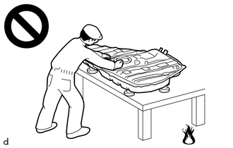
- Vaporized fuel could ignite, resulting in a serious accident.
-
Do not perform work on fuel system components without first disconnecting the cable from the negative (-) auxiliary battery terminal.
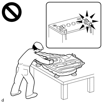
- Sparks could cause vaporized fuel to ignite, resulting in a serious accident.
NOTICE:
- After the ignition switch is turned off, the radio and display receiver assembly records various types of memory and settings. As a result, after turning the ignition switch off, make sure to wait at least 120 seconds before disconnecting the cable from the negative (-) auxiliary battery terminal.
-
This procedure includes the removal of small-head bolts. Refer to Small-Head Bolts of Basic Repair Hint to identify the small-head bolts.
Click here

HINT:
When the cable is disconnected/reconnected to the auxiliary battery terminal, systems temporarily stop operating. However, each system has a function that completes learning the first time the system is used.
-
Learning completes when vehicle is driven
Effect/Inoperative Function When Necessary Procedures are not Performed
Necessary Procedures
Link
Lane tracing assist system
Drive the vehicle straight ahead at 35 km/h (22 mph) or more for 5 second or more.

Pre-collision system
Stop and start system
Drive the vehicle until stop and start control is permitted (approximately 5 to 60 minutes)

-
Learning completes when vehicle is operated normally
Effect/Inoperative Function When Necessary Procedures are not Performed
Necessary Procedures
Link
Power door lock control system
- Back door opener
Perform door unlock operation with door control switch or electrical key transmitter sub-assembly switch.

Air conditioning system
After the ignition switch is turned to ON, the servo motor standard position is recognized.
-
PROCEDURE
1. REMOVE FUEL SUCTION WITH PUMP AND GAUGE TUBE ASSEMBLY
Click here

2. REMOVE FUEL SENDER GAUGE ASSEMBLY
Click here

3. REMOVE FUEL MAIN VALVE ASSEMBLY
| (a) Detach the 2 claws and 2 clamps and disconnect the fuel suction tube from the fuel suction with pump and gauge tube assembly. |
|
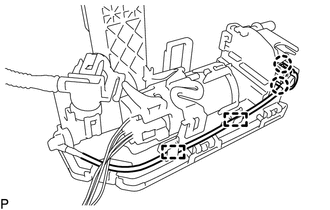
| (b) Remove the O-ring from the fuel suction with pump and gauge tube assembly. |
|
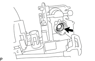
| (c) Detach the 4 claws and disconnect the sub-assembly support from the fuel suction with pump and gauge tube assembly. |
|
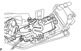
| (d) Detach the 3 claws and remove the No. 3 fuel suction support from the fuel suction with pump and gauge tube assembly. |
|
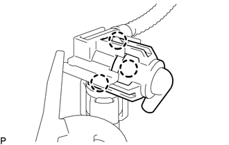
| (e) Remove the fuel main valve assembly from the fuel suction with pump and gauge tube assembly. |
|
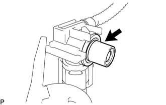
| (f) Remove the O-ring and spacer from the fuel main valve assembly. |
|
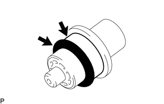
 Components
COMPONENTS ILLUSTRATION
*1 FUEL MAIN VALVE ASSEMBLY *2 FUEL SENDER GAUGE ASSEMBLY *3 FUEL SUCTION WITH PUMP AND GAUGE TUBE ASSEMBLY *4 NO...
 Installation
INSTALLATION PROCEDURE 1. INSTALL FUEL MAIN VALVE ASSEMBLY (a) Apply gasoline to a new O-ring. (b) Install the spacer and O-ring to the fuel main valve assembly...
Other information:
Toyota Yaris XP210 (2020-2026) Owner's Manual: Storage Compartments
WARNING Keep storage boxes closed when driving Driving with the storage boxes open is dangerous. To reduce the possibility of injury in an accident or a sudden stop, keep the storage boxes closed when driving. Do not put articles in storage spaces with no lid Putting articles in storage spaces with no lid is dangerous as they could be thrown around the cabin if the vehicle is suddenly accelerated and cause injury depending on how the article is stored...
Toyota Yaris XP210 (2020-2026) Reapir and Service Manual: Problem Symptoms Table
PROBLEM SYMPTOMS TABLE NOTICE: When replacing the forward recognition camera, always replace it with a new one. If a forward recognition camera which was installed to another vehicle is used, the information stored in the forward recognition camera will not match the information from the vehicle and a DTC may be stored...
Categories
- Manuals Home
- Toyota Yaris Owners Manual
- Toyota Yaris Service Manual
- How to use USB mode
- Battery Monitor Module General Electrical Failure (P058A01)
- Adjustment
- New on site
- Most important about car
Break-In Period
No special break-in is necessary, but a few precautions in the first 600 miles (1,000 km) may add to the performance, economy, and life of the vehicle.
Do not race the engine. Do not maintain one constant speed, either slow or fast, for a long period of time. Do not drive constantly at full-throttle or high engine rpm for extended periods of time. Avoid unnecessary hard stops. Avoid full-throttle starts.