Toyota Yaris: Fuel Main Valve / Components
COMPONENTS
ILLUSTRATION
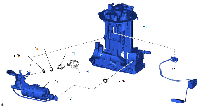
| *1 | FUEL MAIN VALVE ASSEMBLY | *2 | FUEL SENDER GAUGE ASSEMBLY |
| *3 | FUEL SUCTION WITH PUMP AND GAUGE TUBE ASSEMBLY | *4 | NO. 3 FUEL SUCTION SUPPORT |
| *5 | SPACER | *6 | O-RING |
| *7 | SUB-ASSEMBLY SUPPORT | *8 | FUEL SUCTION TUBE |
| ● | Non-reusable part | - | - |

 Removal
REMOVAL CAUTION / NOTICE / HINT CAUTION:
Never perform work on fuel system components near any possible ignition sources.
Vaporized fuel could ignite, resulting in a serious accident...
Other information:
Toyota Yaris XP210 (2020-2026) Reapir and Service Manual: Fail-safe Chart
FAIL-SAFE CHART If any of the following DTCs are stored, the ECM enters fail-safe mode to allow the vehicle to be driven temporarily or stops fuel injection. DTC Code Component Fail-Safe Operation Fail-Safe Deactivation Condition P001100 P001200 VVT system Intake VVT maximum retarded contact...
Toyota Yaris XP210 (2020-2026) Reapir and Service Manual: Steering Pad Switch Circuit
DESCRIPTION The steering pad switch assembly outputs the dynamic cruise control on/off signal and various control signals to the ECM. The ECM controls the dynamic cruise control system according to the signals received from the steering pad switch assembly...
Categories
- Manuals Home
- Toyota Yaris Owners Manual
- Toyota Yaris Service Manual
- Battery Monitor Module General Electrical Failure (P058A01)
- Engine & Hybrid System
- Headlights
- New on site
- Most important about car
Fuel Gauge
The fuel gauge shows approximately how much fuel is remaining in the tank when the ignition is switched ON. We recommend keeping the tank over 1/4 full.

Copyright © 2026 www.toyaris4.com