Toyota Yaris: Charging System / Parts Location
PARTS LOCATION
ILLUSTRATION
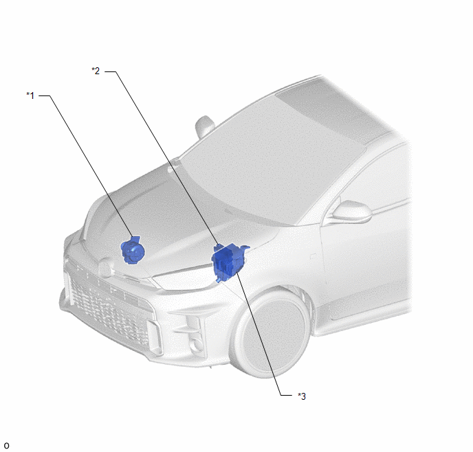
| *1 | GENERATOR ASSEMBLY | *2 | ECM |
| *3 | NO. 1 ENGINE ROOM RELAY BLOCK - EFI NO. 1 FUSE - R/B BATT FUSE - INP STD NO. 1-3 FUSE - ALT FUSE | - | - |
ILLUSTRATION
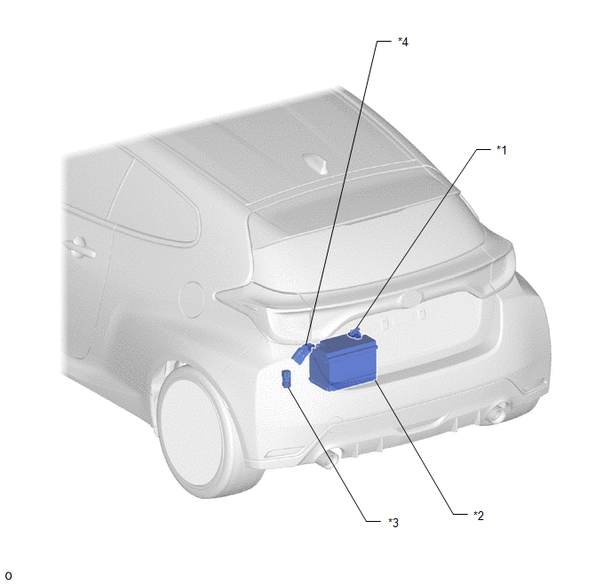
| *1 | BATTERY STATE SENSOR ASSEMBLY | *2 | AUXILIARY BATTERY |
| *3 | NO. 5 ENGINE ROOM RELAY BLOCK - BATT-S NO. 1 FUSE | *4 | FUSIBLE LINK BLOCK ASSEMBLY - R/B RR NO. 1 FUSE |
ILLUSTRATION
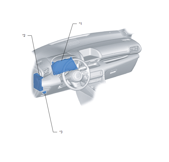
| *1 | COMBINATION METER ASSEMBLY | *2 | POWER DISTRIBUTION BOX ASSEMBLY - ECU-B NO. 2 FUSE |
| *3 | DLC3 | - | - |
 Precaution
PRECAUTION CHARGING SYSTEM PRECAUTION NOTICE:
Check that the battery cables are connected to the correct terminals.
Disconnect the battery cables when the auxiliary battery is given a quick charge...
 System Diagram
S..
Other information:
Toyota Yaris XP210 (2020-2026) Reapir and Service Manual: Charging Control System (P160F00)
DESCRIPTION If the engine stop and start ECU receives a charging control malfunction signal from the ECM, it will blink the stop and start cancel indicator and store DTC P160F00. DTC No. Detection Item DTC Detection Condition Trouble Area Warning Indicate Memory Note P160F00 Charging Control System All of the following conditions are met for 15 seconds or more (1 trip detection logic): Charging control malfunction signal received from the ECM...
Toyota Yaris XP210 (2020-2026) Reapir and Service Manual: Utility
U..
Categories
- Manuals Home
- Toyota Yaris Owners Manual
- Toyota Yaris Service Manual
- To Set Speed
- Fuse Panel Description
- Key Battery Replacement
- New on site
- Most important about car
Break-In Period
No special break-in is necessary, but a few precautions in the first 600 miles (1,000 km) may add to the performance, economy, and life of the vehicle.
Do not race the engine. Do not maintain one constant speed, either slow or fast, for a long period of time. Do not drive constantly at full-throttle or high engine rpm for extended periods of time. Avoid unnecessary hard stops. Avoid full-throttle starts.
Copyright © 2026 www.toyaris4.com