Toyota Yaris: Charging System / System Diagram
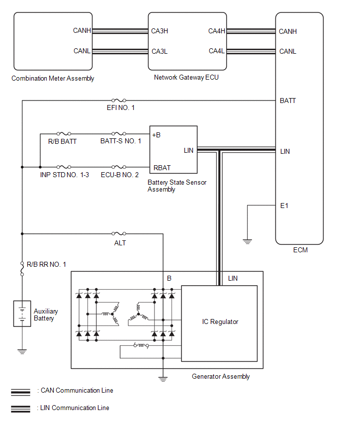
SYSTEM DIAGRAM
 Parts Location
PARTS LOCATION ILLUSTRATION
*1 GENERATOR ASSEMBLY *2 ECM *3 NO. 1 ENGINE ROOM RELAY BLOCK - EFI NO. 1 FUSE - R/B BATT FUSE - INP STD NO...
 How To Proceed With Troubleshooting
CAUTION / NOTICE / HINT HINT: *: Use the GTS. PROCEDURE 1. VEHICLE BROUGHT TO WORKSHOP
NEXT
2. CUSTOMER PROBLEM ANALYSIS HINT:
In troubleshooting, confirm that the problem symptoms have been accurately identified...
Other information:
Toyota Yaris XP210 (2020-2026) Reapir and Service Manual: Brake Switch "A"/"B" Signal Cross Coupled (P05042B)
DESCRIPTION The stop light switch assembly is a duplex system that transmits two signals: STP and ST1-. These two signals are used by the ECM to monitor whether or not the brake system is working properly. If the signals, which indicate the brake pedal is being depressed and released, are detected simultaneously, the ECM interprets this as a malfunction in the stop light switch assembly and stores this DTC...
Toyota Yaris XP210 (2020-2026) Reapir and Service Manual: Components
COMPONENTS ILLUSTRATION *1 ROOF DRIP SIDE MOULDING LH *2 ROOF DRIP SIDE MOULDING RH *3 ROOF TOP MOULDING SUB-ASSEMBLY *4 ROOF ANTENNA ASSEMBLY WITH ANTENNA COVER *5 ROOF OUTSIDE COVER *6 SEAL *7 HOLDER - - N*m (kgf*cm, ft...
Categories
- Manuals Home
- Toyota Yaris Owners Manual
- Toyota Yaris Service Manual
- Diagnostic Trouble Code Chart
- Battery Monitor Module General Electrical Failure (P058A01)
- Brake System Control Module "A" System Voltage System Voltage Low (C137BA2)
- New on site
- Most important about car
Supplemental Restraint System (SRS) Precautions
The front and side supplemental restraint systems (SRS) include different types of air bags. Please verify the different types of air bags which are equipped on your vehicle by locating the “SRS AIRBAG” location indicators. These indicators are visible in the area where the air bags are installed.
The air bags are installed in the following locations:
The steering wheel hub (driver air bag) The front passenger dashboard (front passenger air bag) The outboard sides of the front seatbacks (side air bags) The front and rear window pillars, and the roof edge along both sides (curtain air bags)
Copyright © 2026 www.toyaris4.com