Toyota Yaris: Steering Angle Sensor / Installation
INSTALLATION
CAUTION / NOTICE / HINT
NOTICE:
After performing the update ECU security key procedure, make sure to perform the initialization procedure for when the cable has been disconnected and reconnected to the negative (-) auxiliary battery terminal.
PROCEDURE
1. INSPECT SPIRAL CABLE WITH SENSOR SUB-ASSEMBLY
Click here

2. INSTALL STEERING SENSOR
| (a) Align the 2 pins and 2 guides, and engage the 6 claws to install the steering sensor to the spiral cable sub-assembly. NOTICE:
|
|
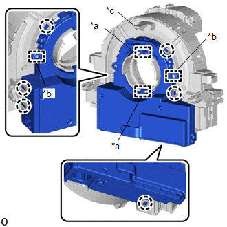
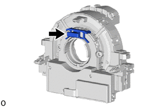
| (b) Remove the lock pin from the steering sensor. |
|
3. PLACE FRONT WHEELS FACING STRAIGHT AHEAD

4. INSTALL SPIRAL CABLE WITH SENSOR SUB-ASSEMBLY
Click here

5. INSTALL UPPER STEERING COLUMN COVER
Click here

6. INSTALL LOWER STEERING COLUMN COVER
Click here

7. ADJUST SPIRAL CABLE WITH SENSOR SUB-ASSEMBLY
Click here

8. INSTALL STEERING WHEEL ASSEMBLY
Click here

9. INSTALL HORN BUTTON ASSEMBLY
Click here

10. CONNECT CABLE TO NEGATIVE AUXILIARY BATTERY TERMINAL
Click here

11. UPDATE ECU SECURITY KEY
Click here

12. INSPECT HORN BUTTON ASSEMBLY
Click here

13. PERFORM DIAGNOSTIC SYSTEM CHECK
Click here

14. CHECK SRS WARNING LIGHT
Click here

15. PERFORM CALIBRATION
Click here

16. INITIALIZATION AFTER RECONNECTING AUXILIARY BATTERY TERMINAL
HINT:
When disconnecting and reconnecting the auxiliary battery, there is an automatic learning function that completes learning when the respective system is used.
Click here

 Removal
REMOVAL CAUTION / NOTICE / HINT The necessary procedures (adjustment, calibration, initialization, or registration) that must be performed after parts are removed, installed, or replaced during the steering angle sensor removal/installation are shown below...

Other information:
Toyota Yaris XP210 (2020-2026) Reapir and Service Manual: Terminals Of Ecm
TERMINALS OF ECM HINT: The standard voltage, resistance and waveform between each pair of the ECM terminals is shown in the table below. The appropriate conditions for checking each pair of the terminals are also indicated. The result of checks should be compared with the standard voltage, resistance and waveform for each pair of the terminals as displayed in the Specified Condition column...
Toyota Yaris XP210 (2020-2026) Reapir and Service Manual: Components
C..
Categories
- Manuals Home
- Toyota Yaris Owners Manual
- Toyota Yaris Service Manual
- Key Battery Replacement
- Engine Start Function When Key Battery is Dead
- Battery Monitor Module General Electrical Failure (P058A01)
- New on site
- Most important about car
Key Suspend Function
If a key is left in the vehicle, the functions of the key left in the vehicle are temporarily suspended to prevent theft of the vehicle.
To restore the functions, press the unlock button on the functions-suspended key in the vehicle.