Toyota Yaris: Turbocharger / Inspection
INSPECTION
PROCEDURE
1. INSPECT TURBOCHARGER SUB-ASSEMBLY
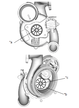
| (a) Check if the compressor side impeller and exhaust side turbine are damaged or defective. HINT: Wear on the center of the exhaust side turbine is not a malfunction. |
|
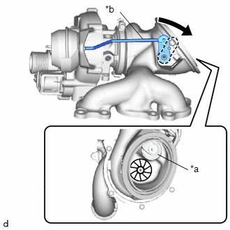
| (b) Move the rod by hand and check that the waste gate valve is not stuck. |
|
| (c) Using a straightedge and feeler gauge, check the turbocharger sub-assembly installation surface for warpage. Standard Warpage: 0.15 mm (0.00591 in.) or less If the result is not as specified, replace the turbocharger sub-assembly. |
|
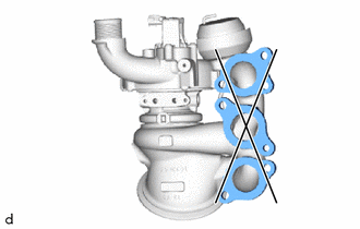
| (d) Close the waste gate valve and using a feeler gauge, measure the clearance between the waste gate valve and the contact surface of the valve port of the turbine with valve housing sub-assembly waste gate. Standard Clearance: 0.15 mm (0.00591 in.) or less If the result is not as specified, replace the turbocharger sub-assembly. |
|
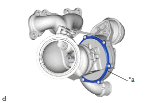
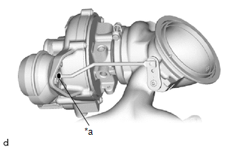
| (e) Check the areas shown in the illustration for oil leakage. OK: There are no oil leaks from the compressor with bearing housing sub-assembly. NOTICE: Oil on the inlet side of the compressor is from oil in the blow-by gas and is not a malfunction. If the result is not as specified, replace the turbocharger sub-assembly. |
|
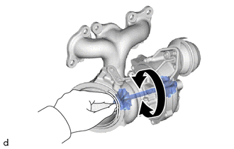
| (f) Rotate the compressor wheel by hand as shown in the illustration, and check that the compressor wheel rotates smoothly. OK: Compressor wheel rotates smoothly. HINT: If the compressor wheel does not rotate smoothly, replace the turbocharger sub-assembly. |
|
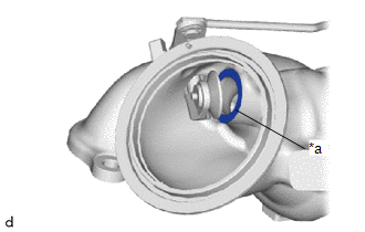
(g) Check that the turbine shaft rotates smoothly.
| (1) Set a dial indicator to the outlet side of the turbine shaft. |
|
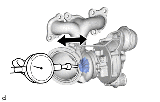
(2) Move the turbine shaft in the axial direction and check for play.
Standard Axial Play:
0.15 mm (0.00591 in.) or less
If the result is not as specified, replace the turbocharger sub-assembly.
2. INSPECT WASTE GATE VALVE ACTUATOR
(a) Check the waste gate valve actuator hose for cracks and damage.
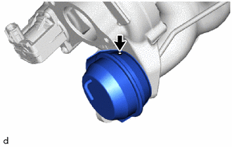
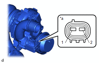
(b) Check the waste gate valve actuator with bracket assembly air hole.
| (1) Check that the waste gate valve actuator air hole shown in the illustration is not clogged. |
|
(c) Check the waste gate valve actuator with bracket assembly travel.
(1) Connect a vacuum pump to the waste gate valve actuator.
| (2) Using a vacuum pump, apply a vacuum of 30 +/- 4.0 kPa (225 +/- 30 mmHg, 8.8 +/- 1.2 in. Hg) to the diaphragm chamber to operate the waste gate valve actuator. OK: The waste gate valve closes when vacuum is applied. NOTICE: Do not apply a vacuum of 65 kPa (488 mmHg, 19.2 in. Hg) or more to the waste gate valve actuator as doing so may damage the diaphragm. HINT: If the waste gate valve actuator does not operate, replace the turbocharger sub-assembly. |
|
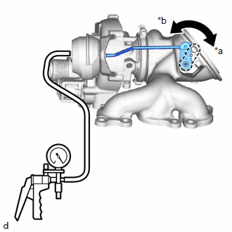
| (3) Place a paint mark on the waste gate valve actuator rod from the waste gate valve actuator bracket as shown in the illustration. |
|
(4) Using a vernier caliper, measure the distance from the waste gate valve actuator bracket to the paint mark at a vacuum of 0 kPa (0 mmHg, 0 in. Hg).
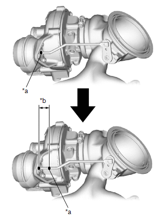
| *a | Paint Mark |
| *b | Travel of Waste Gate Valve Actuator |
 | Vacuum at 0 kPa (0 mmHg, 0 in. Hg) |
Standard:
15 mm (0.591 in.) or more
If the result is not as specified, replace the turbocharger sub-assembly.
NOTICE:
If the result is not as specified when replacing the turbocharger sub-assembly, and check the travel of the waste gate valve actuator again.
(5) Disconnect the vacuum pump from the waste gate valve actuator.
3. INSPECT INTAKE AIR CONTROL VALVE (AIR BY-PASS VALVE ASSEMBLY)
(a) Inspect the resistance.
| (1) Measure the resistance according to the value(s) in the table below. Standard Resistance:
If the result is not as specified, replace the turbocharger sub-assembly. |
|
 Removal
REMOVAL CAUTION / NOTICE / HINT The necessary procedures (adjustment, calibration, initialization or registration) that must be performed after parts are removed and installed, or replaced during exhaust manifold removal/installation are shown below...
 Installation
INSTALLATION PROCEDURE 1. INSTALL STUD BOLT (a) Using an E8 "TORX" socket wrench, install the stud bolt to the turbocharger sub-assembly. Torque: 10 N·m {102 kgf·cm, 7 ft·lbf} 2...
Other information:
Toyota Yaris XP210 (2020-2026) Reapir and Service Manual: Installation
INSTALLATION CAUTION / NOTICE / HINT NOTICE: After replacing the airbag sensor assembly, make sure to perform ECU configuration. After performing the ECU configuration procedure, make sure to perform the initialization procedure for when the cable has been disconnected and reconnected to the negative (-) auxiliary battery terminal...
Toyota Yaris XP210 (2020-2026) Reapir and Service Manual: Adjustment
ADJUSTMENT PROCEDURE 1. INSPECT AND ADJUST BRAKE PEDAL HEIGHT (a) Remove front door scuff plate LH. Click here (b) Remove cowl side trim board LH. Click here (c) Turn back floor carpet. (d) Turn back dash panel insulator assembly. (e) Check the brake pedal height...
Categories
- Manuals Home
- Toyota Yaris Owners Manual
- Toyota Yaris Service Manual
- Key Battery Replacement
- Removal
- How to use USB mode
- New on site
- Most important about car
Fuel-Filler Lid and Cap
WARNING
When removing the fuel-filler cap, loosen the cap slightly and wait for any hissing to stop, then remove it
Fuel spray is dangerous. Fuel can burn skin and eyes and cause illness if ingested. Fuel spray is released when there is pressure in the fuel tank and the fuel-filler cap is removed too quickly.