Toyota Yaris: Turbocharger / Removal
REMOVAL
CAUTION / NOTICE / HINT
The necessary procedures (adjustment, calibration, initialization or registration) that must be performed after parts are removed and installed, or replaced during exhaust manifold removal/installation are shown below.
Necessary Procedures After Parts Removed/Installed/Replaced| Replaced Part or Performed Procedure | Necessary Procedure | Effect/Inoperative Function when Necessary Procedure not Performed | Link |
|---|---|---|---|
| Gas leak from exhaust system is repaired | Inspection After Repair |
|
|

CAUTION:
-
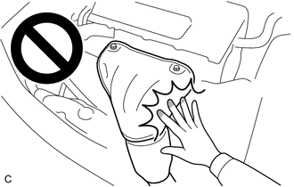
To prevent burns, do not touch the engine, exhaust manifold or other high temperature components while the engine is hot.
-
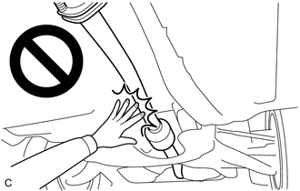
To prevent burns, do not touch the engine, exhaust pipe or other high temperature components while the engine is hot.
PROCEDURE
1. DRAIN ENGINE OIL
Click here

2. DRAIN ENGINE COOLANT
Click here

3. REMOVE EXHAUST MANIFOLD CONVERTER SUB-ASSEMBLY
Click here

4. REMOVE WINDSHIELD WIPER MOTOR AND LINK
Click here

5. REMOVE WATER GUARD PLATE RH
Click here

6. REMOVE NO. 1 FRONT VENTILATOR SEAL
Click here

7. REMOVE OUTER COWL TOP PANEL SUB-ASSEMBLY
Click here

8. REMOVE DASH PANEL HEAT INSULATOR
| (a) Disengage the clamp. |
|
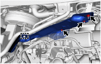
(b) Remove the 3 nuts and dash panel heat insulator.
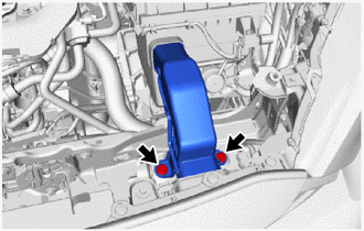
9. REMOVE NO. 1 AIR CLEANER INLET
| (a) Remove the 2 clips and No. 1 air cleaner inlet. |
|
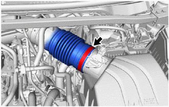
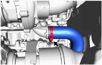
10. SEPARATE NO. 1 AIR CLEANER HOSE
| (a) Loosen the hose clamp to separate the No. 1 air cleaner hose from the air cleaner cap sub-assembly. |
|
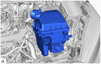
11. REMOVE AIR CLEANER CASE SUB-ASSEMBLY
| (a) Disconnect the 3 connectors and disengage the 6 clamps. |
|
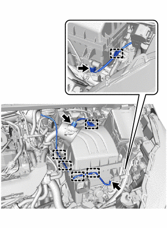
| (b) Remove the air cleaner case sub-assembly. |
|
12. REMOVE INTAKE AIR RESONATOR
| (a) Remove the 2 bolts. |
|
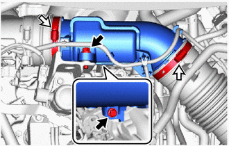
(b) Loosen the 2 hose clamps to remove the intake air resonator.
13. DISCONNECT NO. 1 AIR INLET DUCT
| (a) Remove the bolt. |
|
(b) Slide the hose clip to disconnect the ventilation hose.
(c) Loosen the 2 hose clamps to remove the No. 1 air inlet duct.
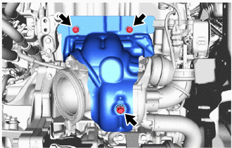
14. REMOVE NO. 1 TURBO INSULATOR
| (a) Remove the 3 bolts and No. 1 turbo insulator. |
|
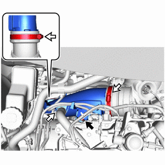
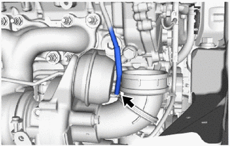
15. SEPARATE TURBO OIL OUTLET PIPE
| (a) Remove the 2 bolts to separate the turbo oil outlet pipe from the turbocharger sub-assembly. |
|
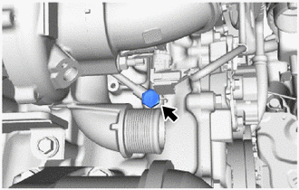
16. DISCONNECT NO. 2 AIR HOSE
| (a) Loosen the hose clamp to disconnect the No. 2 air hose. |
|
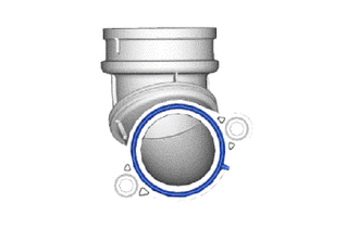
17. DISCONNECT NO. 2 VACUUM TRANSMITTING HOSE
| (a) Disconnect the No. 2 vacuum transmitting hose. |
|
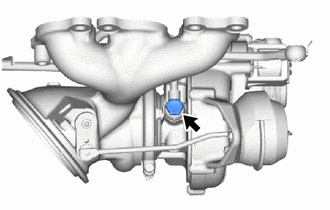
18. REMOVE TURBO OIL INLET PIPE UNION BOLT
| (a) Remove the turbo oil inlet pipe union bolt. |
|
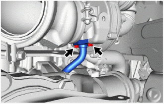
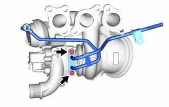
19. DISCONNECT NO. 1 TURBO WATER PIPE SUB-ASSEMBLY
| (a) Slide the hose clip to disconnect the No. 1 turbo water hose. |
|
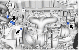
(b) Remove the bolt and union bolt to disconnect the No. 1 turbo water pipe sub-assembly.
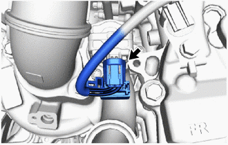
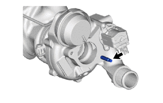
20. DISCONNECT WIRE HARNESS
| (a) Disconnect the connector. |
|
21. REMOVE TURBOCHARGER SUB-ASSEMBLY
| (a) Remove the 7 nuts. |
|
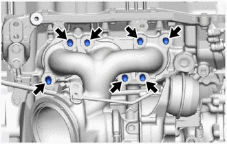
(b) Remove the collar.
| (c) Using an E8 "TORX" socket wrench, remove the 7 stud bolts. |
|
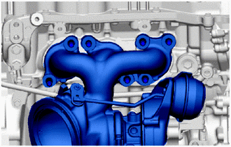
(d) Remove the turbocharger sub-assembly.
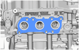
22. REMOVE EXHAUST MANIFOLD TO HEAD GASKET
| (a) Remove the exhaust manifold to head gasket. |
|
23. DISCONNECT COMPRESSOR INLET ELBOW
| (a) Remove the bolt, nut and compressor inlet elbow. |
|
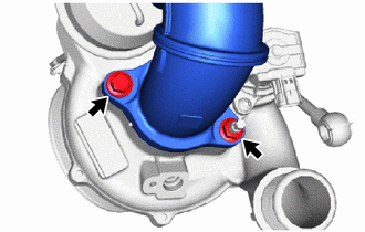
| (b) Remove the gasket. |
|
24. REMOVE TURBO OIL INLET PIPE SUB-ASSEMBLY
| (a) Remove the union bolt and turbo oil inlet pipe sub-assembly. |
|
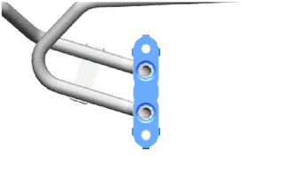
25. REMOVE NO. 1 TURBO WATER PIPE SUB-ASSEMBLY
| (a) Remove the 2 bolts and No. 1 turbo water pipe sub-assembly. |
|
26. REMOVE TURBO WATER PIPE GASKET
| (a) Remove the turbo water pipe gasket from the No. 1 turbo water pipe sub-assembly. |
|
27. REMOVE STUD BOLT
| (a) Using an E8 "TORX" socket wrench, remove the stud bolt from the turbocharger sub-assembly. |
|
 On-vehicle Inspection
ON-VEHICLE INSPECTION CAUTION / NOTICE / HINT CAUTION: To prevent injury due to contact with an operating V-ribbed belt or cooling fan, keep your hands and clothing away from the V-ribbed belt and cooling fan when working in the engine compartment with the engine running or the ignition switch ON...
 Inspection
INSPECTION PROCEDURE 1. INSPECT TURBOCHARGER SUB-ASSEMBLY (a) Check if the compressor side impeller and exhaust side turbine are damaged or defective...
Other information:
Toyota Yaris XP210 (2020-2026) Reapir and Service Manual: Installation
INSTALLATION PROCEDURE 1. INSTALL FRONT BUMPER ASSEMBLY (a) Install the 3 grommets. HINT: Use the same procedure for the RH side and LH side. (b) Temporarily install the front bumper assembly with the 2 clips and 2 bolts. (c) w/ Pre-collision System: (1) Connect the connector...
Toyota Yaris XP210 (2020-2026) Reapir and Service Manual: Components
COMPONENTS ILLUSTRATION *1 FUEL PUMP *2 FUEL SUCTION WITH PUMP AND GAUGE TUBE ASSEMBLY *3 FUEL SENDER GAUGE ASSEMBLY *4 CANISTER (FUEL SUCTION WITH PUMP AND GAUGE TUBE ASSEMBLY) *5 FUEL MAIN VALVE ASSEMBLY *6 NO. 3 FUEL SUCTION SUPPORT *7 WIRE HARNESS *8 SPACER *9 O-RING *10 SUB-ASSEMBLY SUPPORT *11 NO...
Categories
- Manuals Home
- Toyota Yaris Owners Manual
- Toyota Yaris Service Manual
- Battery Monitor Module General Electrical Failure (P058A01)
- Maintenance
- Headlights
- New on site
- Most important about car
Key Suspend Function
If a key is left in the vehicle, the functions of the key left in the vehicle are temporarily suspended to prevent theft of the vehicle.
To restore the functions, press the unlock button on the functions-suspended key in the vehicle.