Toyota Yaris: Steering Gear / Installation
INSTALLATION
PROCEDURE
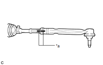
1. INSTALL TIE ROD END SUB-ASSEMBLY LH
| (a) Install the lock nut and tie rod end sub-assembly LH to the steering gear assembly until the matchmarks are aligned. HINT: After adjusting the toe-in, tighten the lock nut. |
|
2. INSTALL TIE ROD END SUB-ASSEMBLY RH
HINT:
Perform the same procedure as for the LH side.
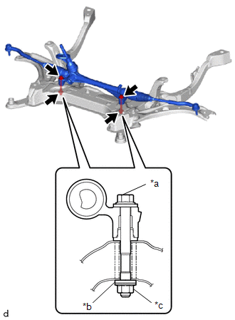
3. INSTALL STEERING LINK ASSEMBLY
| (a) Install the steering link assembly to the front suspension crossmember sub-assembly with the 2 bolts, 2 washers and 2 nuts. Torque: 79 N·m {806 kgf·cm, 58 ft·lbf} NOTICE:
|
|
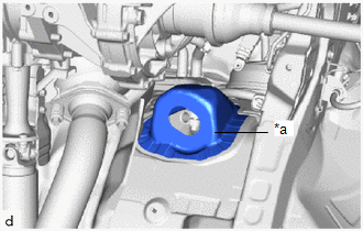
4. INSTALL STEERING COLUMN HOLE COVER
(a) Align the protrusion of the steering link assembly with the hole of the steering column hole cover, and install the steering column hole cover to the steering link assembly.
HINT:
-
Check that there is no foreign matter adhering to the seal portions of the steering column hole cover or dash panel.
*a
Dash Panel
-
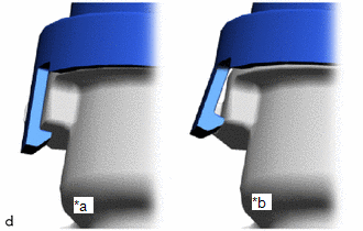
After installing the steering column hole cover, check that the claws of the steering column hole cover base are not disengaged.
*a
OK
*b
NG
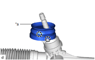
| *a | Seal Portions |
5. INSTALL FRONT SUSPENSION CROSSMEMBER SUB-ASSEMBLY
Click here

6. INSPECT AND ADJUST FRONT WHEEL ALIGNMENT
Click here

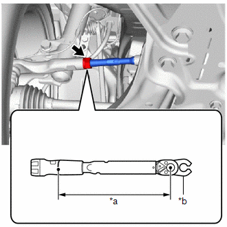
7. FULLY TIGHTEN TIE ROD END SUB-ASSEMBLY LH
| (a) Using a union nut wrench, tighten the tie rod end sub-assembly lock nuts. Torque: Specified Tightening Torque : 74.5 N·m {760 kgf·cm, 55 ft·lbf} NOTICE: Make sure that the boots are not twisted. HINT:
|
|

8. FULLY TIGHTEN TIE ROD END SUB-ASSEMBLY RH
HINT:
Perform the same procedure as for the LH side.