Toyota Yaris: Power Mirror Control System / Mirror Heater does not Operate with Rear Defogger Switch
DESCRIPTION
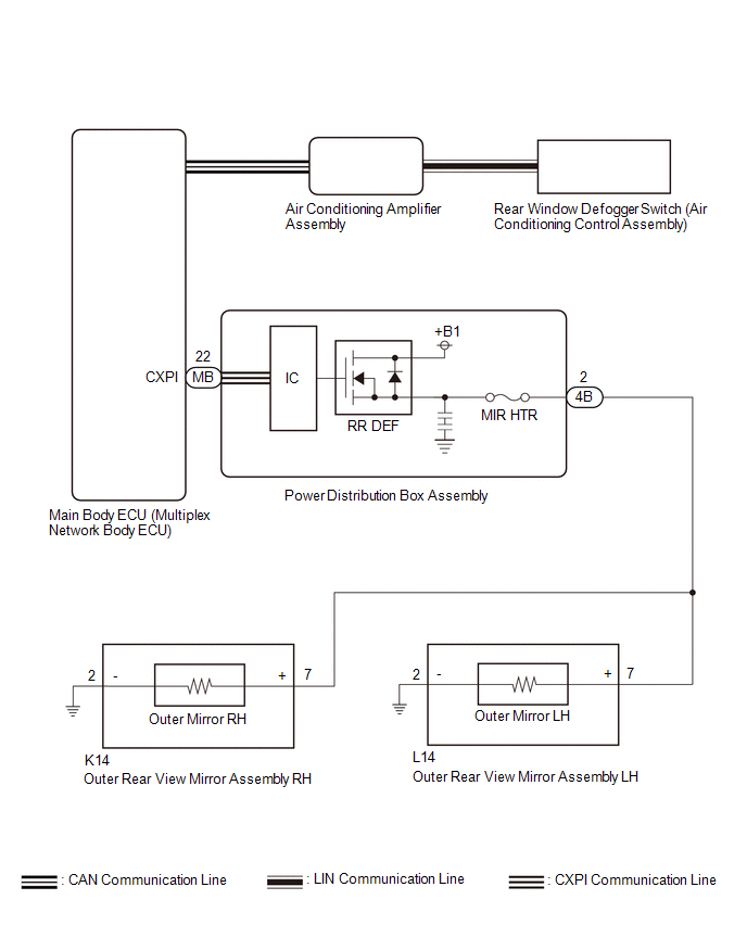
When the mirror heater switch (rear window defogger switch) is operated, the RR DEF relay drive request signal is sent to the air conditioning amplifier assembly and then to main body ECU (multiplex network body ECU) via CAN communication. When the main body ECU (multiplex network body ECU) receives the RR DEF relay drive request signal, it sends a mirror heater operation signal to the power distribution box assembly.
Based on this signal, the power distribution box assembly operate the mirror heaters.
WIRING DIAGRAM
CAUTION / NOTICE / HINT
NOTICE:
- Inspect the fuses for circuits related to this system before performing the following procedure.
- If the auxiliary battery voltage becomes low, auxiliary battery load control will operate in order to ensure sufficient power is supplied to the power steering system. In this case, the window defogger system may not operate.
-
The power mirror control system uses the CAN communication system, LIN communication system and CXPI communication system. Inspect the communication function by following How to Proceed with Troubleshooting. Troubleshoot the power mirror control system after confirming that the communication system is functioning properly.
Click here
.gif)
PROCEDURE
| 1. | CHECK VEHICLE CONDITION |
(a) Check vehicle condition.
| Result | Proceed to |
|---|---|
| Both mirror heater does not operate | A |
| LH side mirror heater does not operate | B |
| RH side mirror heater does not operate | C |
| B |
.gif) | GO TO STEP 6 |
| C |
| GO TO STEP 8 |
|
.gif)
| 2. | CHECK WINDOW DEFOGGER SYSTEM |
(a) Check the window defogger system operation.
Click here
OK:
The window defogger system operates normally.
| NG |
| GO TO WINDOW DEFOGGER SYSTEM |
|
| 3. | CHECK HARNESS AND CONNECTOR (OUTER REAR VIEW MIRROR ASSEMBLY - POWER DISTRIBUTION BOX ASSEMBLY AND BODY GROUND) |
(a) Disconnect the L14 outer rear view mirror assembly LH connector.
(b) Disconnect the K14 outer rear view mirror assembly RH connector.
(c) Disconnect the 4B power distribution box assembly connector.
(d) Measure the resistance according to the value(s) in the table below.
Standard Resistance:
LH Side| Tester Connection | Condition | Specified Condition |
|---|---|---|
| L14-7 (+) - 4B-2 | Always | Below 1 Ω |
| L14-2 (-) - Body Ground | Always | Below 1 Ω |
| L14-7 (+) or 4B-2 - Body ground | Always | 10 kΩ or higher |
| Tester Connection | Condition | Specified Condition |
|---|---|---|
| K14-7 (+) - 4B-2 | Always | Below 1 Ω |
| K14-2 (-) - Body Ground | Always | Below 1 Ω |
| K14-7 (+) or 4B-2 - Body ground | Always | 10 kΩ or higher |
| NG |
| REPAIR OR REPLACE HARNESS OR CONNECTOR |
|
| 4. | INSPECT OUTER REAR VIEW MIRROR ASSEMBLY LH |
Click here
| NG |
| GO TO STEP 7 |
|
| 5. | INSPECT OUTER REAR VIEW MIRROR ASSEMBLY RH |
Click here
| OK |
| REPLACE POWER DISTRIBUTION BOX ASSEMBLY |
| NG |
| GO TO STEP 9 |
| 6. | CHECK HARNESS AND CONNECTOR (OUTER REAR VIEW MIRROR ASSEMBLY LH - POWER DISTRIBUTION BOX ASSEMBLY) |
(a) Disconnect the L14 outer rear view mirror assembly LH connector.
(b) Disconnect the 4B power distribution box assembly connector.
(c) Measure the resistance according to the value(s) in the table below.
Standard Resistance:
| Tester Connection | Condition | Specified Condition |
|---|---|---|
| L14-7 (+) - 4B-2 | Always | Below 1 Ω |
| L14-2 (-) - Body Ground | Always | Below 1 Ω |
| NG |
| REPAIR OR REPLACE HARNESS OR CONNECTOR |
|
| 7. | INSPECT OUTER MIRROR LH |
Click here
| OK |
| REPLACE OUTER REAR VIEW MIRROR ASSEMBLY LH |
| NG |
| REPLACE OUTER MIRROR LH |
| 8. | CHECK HARNESS AND CONNECTOR (OUTER REAR VIEW MIRROR ASSEMBLY RH - POWER DISTRIBUTION BOX ASSEMBLY) |
(a) Disconnect the K14 outer rear view mirror assembly RH connector.
(b) Disconnect the 4B power distribution box assembly connector.
(c) Measure the resistance according to the value(s) in the table below.
Standard Resistance:
| Tester Connection | Condition | Specified Condition |
|---|---|---|
| K14-7 (+) - 4B-2 | Always | Below 1 Ω |
| K14-2 (-) - Body Ground | Always | Below 1 Ω |
| NG |
| REPAIR OR REPLACE HARNESS OR CONNECTOR |
|
| 9. | INSPECT OUTER MIRROR RH |
Click here
| OK |
| REPLACE OUTER REAR VIEW MIRROR ASSEMBLY RH |
| NG |
| REPLACE OUTER MIRROR RH |
 Data List / Active Test
DATA LIST / ACTIVE TEST DATA LIST NOTICE: In the table below, the values listed under "Normal Condition" are reference values. Do not depend solely on these reference values when deciding whether a part is faulty or not...
 Power Retractable Mirrors do not Operate with Power Retract Mirror Switch
DESCRIPTION When the outer mirror switch assembly is operated, the mirror retract/return signal is sent to the main body ECU (multiplex network body ECU) and then to power distribution box assembly via CXPI communication...
Other information:
Toyota Yaris XP210 (2020-2026) Owner's Manual: Vehicle Loading
This section will guide you in the proper loading of your vehicle, to keep your loaded vehicle weight within its design rating capability. Properly loading your vehicle will provide maximum return of vehicle design performance. Before loading your vehicle, familiarize yourself with the following terms for determining your vehicle’s weight ratings, from the vehicle’s Safety Certification Label and Tire and Load Information Label: Base Curb Weight is the weight of the vehicle including a full tank of fuel and all standard equipment...
Toyota Yaris XP210 (2020-2026) Reapir and Service Manual: Pcv Valve
ComponentsCOMPONENTS ILLUSTRATION *1 PCV VALVE (VENTILATION VALVE SUB-ASSEMBLY) - - On-vehicle InspectionON-VEHICLE INSPECTION PROCEDURE 1. INSPECT PCV VALVE (VENTILATION VALVE SUB-ASSEMBLY) (a) Check the PCV valve (ventilation valve sub-assembly) operation...
Categories
- Manuals Home
- Toyota Yaris Owners Manual
- Toyota Yaris Service Manual
- Engine Start Function When Key Battery is Dead
- Adjustment
- Fuel Gauge
- New on site
- Most important about car
Fuel Gauge
The fuel gauge shows approximately how much fuel is remaining in the tank when the ignition is switched ON. We recommend keeping the tank over 1/4 full.
