Toyota Yaris: Power Mirror Control System / Power Retractable Mirrors do not Operate with Power Retract Mirror Switch
DESCRIPTION
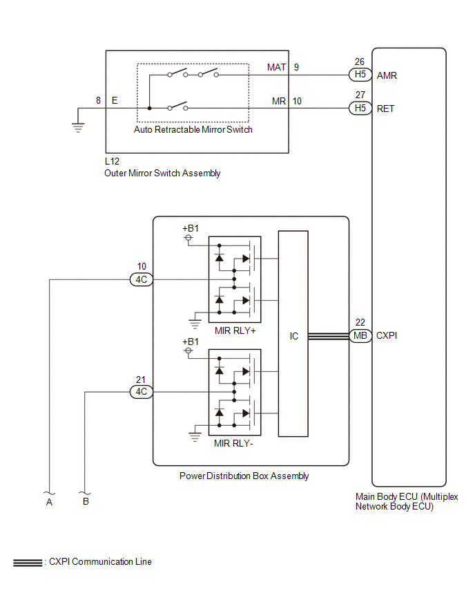
When the outer mirror switch assembly is operated, the mirror retract/return signal is sent to the main body ECU (multiplex network body ECU) and then to power distribution box assembly via CXPI communication.
The power distribution box assembly retracts or returns the outer rear view mirror assemblies based on the signal.
WIRING DIAGRAM
CAUTION / NOTICE / HINT
NOTICE:
- Inspect the fuses for circuits related to this system before performing the following procedure.
-
If the main body ECU (multiplex network body ECU) is replaced, refer to the Registration.
Click here
.gif)
- The power mirror control system uses the CXPI communication system. Inspect the communication function by following How to Proceed with Troubleshooting. Troubleshoot the power mirror control system after confirming that the communication system is functioning properly.
PROCEDURE
| 1. | READ VALUE USING GTS (Outer Mirror Fold Switch) |
(a) Read the Data List according to the display on the GTS.
Body Electrical > Main Body > Data List| Tester Display | Measurement Item | Range | Normal Condition | Diagnostic Note |
|---|---|---|---|---|
| Outer Mirror Fold Switch | Retractable outer mirror switch signal | OFF or ON | OFF: Retractable outer mirror switch not in retract position ON: Retractable outer mirror switch in retract position | - |
| Tester Display |
|---|
| Outer Mirror Fold Switch |
OK:
On the GTS screen, ON or OFF is displayed accordingly.
| NG |
.gif) | GO TO STEP 12 |
|
.gif)
| 2. | CHECK VEHICLE CONDITION |
(a) Check the malfunctioning parts.
| Result | Proceed to |
|---|---|
| Both outer rear view mirror assemblies are malfunctioning | A |
| Outer rear view mirror assembly LH is malfunctioning | B |
| Outer rear view mirror assembly RH is malfunctioning | C |
| B |
| GO TO STEP 8 |
| C |
| GO TO STEP 10 |
|
| 3. | PERFORM ACTIVE TEST USING GTS |
(a) Perform the Active Test according to the display on the GTS.
Body Electrical > Main Body > Active Test| Tester Display | Measurement Item | Control Range | Diagnostic Note |
|---|---|---|---|
| Mirror Fold Signal | Retract mirror operation | OFF or ON | - |
| Mirror Return Signal | Retract mirror operation | OFF or ON | - |
| Tester Display |
|---|
| Mirror Fold Signal |
| Tester Display |
|---|
| Mirror Return Signal |
| OK |
| REPLACE MAIN BODY ECU (MULTIPLEX NETWORK BODY ECU) |
|
| 4. | READ VALUE USING GTS (Power Retract Mirror Input Signal) |
(a) Read the Data List according to the display on the GTS.
Body Electrical > Power Distribution Box > Data List| Tester Display | Measurement Item | Range | Normal Condition | Diagnostic Note |
|---|---|---|---|---|
| Power Retract Mirror Input Signal | Power retract mirror drive signal (Input) | Stop, Retract, Return | Stop: Outer rear view mirror assembly not move Retract: Outer mirror switch in retract position Return: Outer mirror switch in return position | - |
| Tester Display |
|---|
| Power Retract Mirror Input Signal |
OK:
The GTS display changes correctly according to the outer mirror switch assembly operation.
| NG |
| REPLACE MAIN BODY ECU (MULTIPLEX NETWORK BODY ECU) |
|
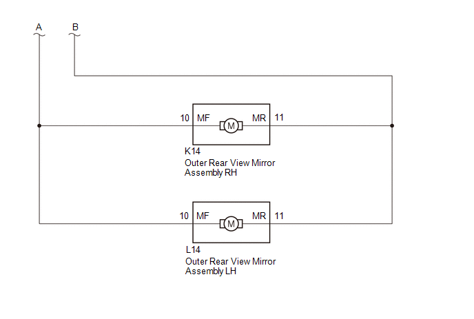
| 5. | CHECK HARNESS AND CONNECTOR (POWER DISTRIBUTION BOX ASSEMBLY - OUTER REAR VIEW MIRROR ASSEMBLY) |
(a) Disconnect the 4C power distribution box assembly connector.
(b) Disconnect the L14 outer rear view mirror assembly LH connector.
(c) Disconnect the K14 outer rear view mirror assembly RH connector.
(d) Measure the resistance according to the value(s) in the table below.
Standard Resistance:
| Tester Connection | Condition | Specified Condition |
|---|---|---|
| 4C-10 - L14-10 (MF) | Always | Below 1 Ω |
| 4C-10 - K14-10 (MF) | Always | Below 1 Ω |
| 4C-21 - L14-11 (MR) | Always | Below 1 Ω |
| 4C-21 - K14-11 (MR) | Always | Below 1 Ω |
| 4C-10 - Body Ground | Always | 10 kΩ or higher |
| 4C-21 - Body Ground | Always | 10 kΩ or higher |
| NG |
| REPAIR OR REPLACE HARNESS OR CONNECTOR |
|
| 6. | INSPECT OUTER REAR VIEW MIRROR ASSEMBLY LH |
Click here
| NG |
| REPLACE OUTER REAR VIEW MIRROR ASSEMBLY LH |
|
| 7. | INSPECT OUTER REAR VIEW MIRROR ASSEMBLY RH |
Click here
| OK |
| REPLACE POWER DISTRIBUTION BOX ASSEMBLY |
| NG |
| REPLACE OUTER REAR VIEW MIRROR ASSEMBLY RH |
| 8. | INSPECT OUTER REAR VIEW MIRROR ASSEMBLY LH |
Click here
| NG |
| REPLACE OUTER REAR VIEW MIRROR ASSEMBLY LH |
|
| 9. | CHECK HARNESS AND CONNECTOR (POWER DISTRIBUTION BOX ASSEMBLY - OUTER REAR VIEW MIRROR ASSEMBLY LH) |
(a) Disconnect the 4C power distribution box assembly connector.
(b) Measure the resistance according to the value(s) in the table below.
Standard Resistance:
| Tester Connection | Condition | Specified Condition |
|---|---|---|
| 4C-10 - L14-10 (MF) | Always | Below 1 Ω |
| 4C-21 - L14-11 (MR) | Always | Below 1 Ω |
| OK |
| USE SIMULATION METHOD TO CHECK |
| NG |
| REPAIR OR REPLACE HARNESS OR CONNECTOR |
| 10. | INSPECT OUTER REAR VIEW MIRROR ASSEMBLY RH |
Click here
| NG |
| REPLACE OUTER REAR VIEW MIRROR ASSEMBLY RH |
|
| 11. | CHECK HARNESS AND CONNECTOR (POWER DISTRIBUTION BOX ASSEMBLY - OUTER REAR VIEW MIRROR ASSEMBLY RH) |
(a) Disconnect the 4C power distribution box assembly connector.
(b) Measure the resistance according to the value(s) in the table below.
Standard Resistance:
| Tester Connection | Condition | Specified Condition |
|---|---|---|
| 4C-10 - K14-10 (MF) | Always | Below 1 Ω |
| 4C-21 - K14-11 (MR) | Always | Below 1 Ω |
| OK |
| USE SIMULATION METHOD TO CHECK |
| NG |
| REPAIR OR REPLACE HARNESS OR CONNECTOR |
| 12. | INSPECT OUTER MIRROR SWITCH ASSEMBLY |
Click here
| NG |
| REPLACE OUTER MIRROR SWITCH ASSEMBLY |
|
| 13. | CHECK HARNESS AND CONNECTOR (OUTER MIRROR SWITCH ASSEMBLY - MAIN BODY ECU (MULTIPLEX NETWORK BODY ECU)) |
(a) Disconnect the H5 main body ECU (multiplex network body ECU).
(b) Measure the resistance according to the value(s) in the table below.
Standard Resistance:
| Tester Connection | Condition | Specified Condition |
|---|---|---|
| L12-9 (MAT) - H5-26 (AMR) | Always | Below 1 Ω |
| L12-10 (MR) - H5-27 (RET) | Always | Below 1 Ω |
| L12-8 (E) - Body ground | Always | Below 1 Ω |
| L12-9 (MAT) or H5-26 (AMR) - Body ground | Always | 10 kΩ or higher |
| L12-10 (MR) or H5-27 (RET) - Body ground | Always | 10 kΩ or higher |
| OK |
| REPLACE MAIN BODY ECU (MULTIPLEX NETWORK BODY ECU) |
| NG |
| REPAIR OR REPLACE HARNESS OR CONNECTOR |
 Mirror Heater does not Operate with Rear Defogger Switch
DESCRIPTION When the mirror heater switch (rear window defogger switch) is operated, the RR DEF relay drive request signal is sent to the air conditioning amplifier assembly and then to main body ECU (multiplex network body ECU) via CAN communication...
 AUTO Power Retract Mirrors do not operate
DESCRIPTION The outer mirror switch assembly sends a mirror auto retract/return signal to the main body ECU (multiplex network body ECU) when the retractable outer mirror switch on the outer mirror switch assembly is in the AUTO position...
Other information:
Toyota Yaris XP210 (2020-2025) Owner's Manual: How to use Android Auto™ mode
What is Android Auto™? Android Auto™ is an application which allows the operation of an Android™ Smartphone using the vehicle’s audio. Android Auto™ functions such as the phone, messages, music, and map can be used with the vehicle’s audio system...
Toyota Yaris XP210 (2020-2025) Reapir and Service Manual: Components
COMPONENTS ILLUSTRATION *1 NO. 1 SIDE DEFROSTER NOZZLE DUCT *2 NO. 2 SIDE DEFROSTER NOZZLE DUCT *3 ANTENNA CORD SUB-ASSEMBLY - - ILLUSTRATION *1 NO. 2 ANTENNA CORD SUB-ASSEMBLY *2 NO. 8 ANTENNA CORD SUB-ASSEMBLY N*m (kgf*cm, ft...
Categories
- Manuals Home
- Toyota Yaris Owners Manual
- Toyota Yaris Service Manual
- Engine & Hybrid System
- Battery Monitor Module General Electrical Failure (P058A01)
- Fuse Panel Description
- New on site
- Most important about car
Break-In Period
No special break-in is necessary, but a few precautions in the first 600 miles (1,000 km) may add to the performance, economy, and life of the vehicle.
Do not race the engine. Do not maintain one constant speed, either slow or fast, for a long period of time. Do not drive constantly at full-throttle or high engine rpm for extended periods of time. Avoid unnecessary hard stops. Avoid full-throttle starts.