Toyota Yaris: G16e-gts (engine Control) / Relay
Inspection
INSPECTION
PROCEDURE
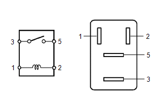
1. INSPECT NO.1 ELECTRONIC FUEL INJECTION MAIN RELAY (EFI-MAIN NO. 1)
| (a) Measure the resistance according to the value(s) in the table below. Standard Resistance:
If the result is not as specified, replace the No.1 electronic fuel injection main relay (EFI-MAIN NO. 1). |
|

2. INSPECT NO.2 ELECTRONIC FUEL INJECTION MAIN RELAY (EFI-MAIN NO. 2)
| (a) Measure the resistance according to the value(s) in the table below. Standard Resistance:
If the result is not as specified, replace the No.2 electronic fuel injection main relay (EFI-MAIN NO. 2). |
|

3. INSPECT NO.3 ELECTRONIC FUEL INJECTION MAIN RELAY (EFI-MAIN NO. 3)
| (a) Measure the resistance according to the value(s) in the table below. Standard Resistance:
If the result is not as specified, replace the No.3 electronic fuel injection main relay (EFI-MAIN NO. 3). |
|

4. INSPECT IGP RELAY
| (a) Measure the resistance according to the value(s) in the table below. Standard Resistance:
If the result is not as specified, replace the igp relay. |
|
 Installation
INSTALLATION PROCEDURE 1. INSTALL MASS AIR FLOW METER (a) Install the mass air flow meter to the air cleaner cap sub-assembly with the 2 screws. NOTICE:
If the mass air flow meter has been struck or dropped, replace it...
 Sfi System
..
Other information:
Toyota Yaris XP210 (2020-2026) Reapir and Service Manual: How To Proceed With Troubleshooting
CAUTION / NOTICE / HINT HINT: Replace parts related to the wireless door lock and smart key system according to the inspection procedure. If the wireless door lock and smart key system does not operate, first check the customize item and make sure that the wireless door lock and smart key system is not turned off...
Toyota Yaris XP210 (2020-2026) Reapir and Service Manual: Installation
INSTALLATION CAUTION / NOTICE / HINT NOTICE: This procedure includes the installation of small-head bolts. Refer to Small-Head Bolts of Basic Repair Hint to identify the small-head bolts. Click here PROCEDURE 1. TEMPORARILY INSTALL FUEL PUMP ASSEMBLY NOTICE: When replacing the fuel pump assembly, it is necessary to replace the No...
Categories
- Manuals Home
- Toyota Yaris Owners Manual
- Toyota Yaris Service Manual
- Removal
- How to connect USB port/Auxiliary jack
- Headlights
- New on site
- Most important about car
Refueling
Before refueling, close all the doors, windows, and the liftgate/trunk lid, and switch the ignition OFF.
To open the fuel-filler lid, pull the remote fuel-filler lid release.
