Toyota Yaris: Headlight Leveling Switch / Inspection
INSPECTION
PROCEDURE
1. INSPECT HEADLIGHT LEVELING SWITCH
(a) Check the voltage.
| (1) Connect a positive (+) lead from the auxiliary battery to terminal 5 (B) and a negative (-) lead to terminal 2 (E). |
|
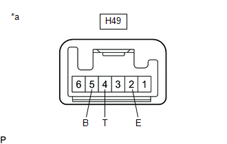
(2) Measure the voltage according to the value(s) in the table below.
Standard Voltage:
| Tester Connection | Condition | Specified Condition |
|---|---|---|
| H49-4 (T) - H49-2 (E) | 0 | 2.40 to 3.12 V |
| H49-4 (T) - H49-2 (E) | 1 | 3.82 to 4.54 V |
| H49-4 (T) - H49-2 (E) | 2 | 5.23 to 5.95 V |
| H49-4 (T) - H49-2 (E) | 3 | 6.65 to 7.37 V |
| H49-4 (T) - H49-2 (E) | 4 | 8.06 to 8.78 V |
| H49-4 (T) - H49-2 (E) | 5 | 9.48 to 10.20 V |
HINT:
Auxiliary battery voltage is 12 V.
If the result is not as specified, replace the headlight leveling switch.
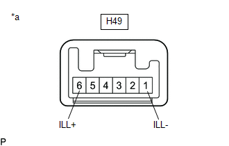
(b) Check the illumination.
| (1) Apply auxiliary battery voltage to the headlight leveling switch and check that the switch illuminates. OK:
If the result is not as specified, replace the headlight leveling switch. |
|
 Removal
REMOVAL PROCEDURE 1. REMOVE CENTER LOWER INSTRUMENT COVER Click here
2. REMOVE LOWER INSTRUMENT PANEL FINISH PANEL Click here
3. REMOVE SWITCH HOLE BASE SUB-ASSEMBLY Click here
4...
 Installation
INSTALLATION PROCEDURE 1. INSTALL HEADLIGHT LEVELING SWITCH (a) Engage the claws to install the headlight leveling switch.
2. INSTALL LOWER INSTRUMENT PANEL FINISH PANEL ASSEMBLY Click here
3...
Other information:
Toyota Yaris XP210 (2020-2026) Reapir and Service Manual: Reassembly
REASSEMBLY CAUTION / NOTICE / HINT HINT: Use the same procedure for the RH and LH sides. The procedure listed below is for the LH side. PROCEDURE 1. INSTALL LICENSE PLATE LIGHT BULB (a) Install the license plate light bulb. 2. INSTALL LICENSE PLATE LIGHT LENS (a) Engage the claws to install the license plate light lens...
Toyota Yaris XP210 (2020-2026) Reapir and Service Manual: Data List / Active Test
DATA LIST / ACTIVE TEST DATA LIST HINT: Using the GTS to read the Data List allows the values or states of switches, sensors, actuators and other items to be read without removing any parts. This non-intrusive inspection can be very useful because intermittent conditions or signals may be discovered before parts or wiring is disturbed...
Categories
- Manuals Home
- Toyota Yaris Owners Manual
- Toyota Yaris Service Manual
- Battery Monitor Module General Electrical Failure (P058A01)
- Immobilizer System
- Auto Lock/Unlock Function
- New on site
- Most important about car
Front Seat Belt Pretensioners
The front seat belt pretensioners are designed to deploy in moderate or severe frontal, near frontal collisions.
In addition, the pretensioners operate when a side collision or a rollover accident is detected. The pretensioners operate differently depending on what types of air bags are equipped. For more details about the seat belt pretensioner operation, refer to the SRS Air Bag Deployment Criteria.