Toyota Yaris: Manual Transaxle Unit / Disassembly
DISASSEMBLY
PROCEDURE
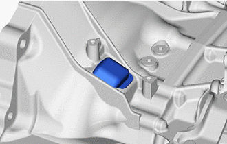
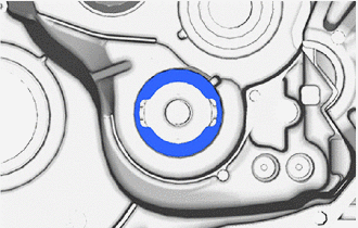
1. REMOVE NO. 1 CLUTCH HOUSING COVER
| (a) Remove the No. 1 clutch housing cover from the front transaxle case. |
|
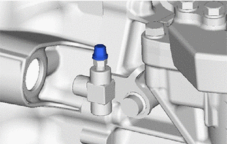
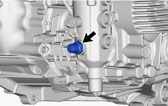
2. REMOVE RELEASE CYLINDER BLEEDER PLUG CAP
| (a) Remove the release cylinder bleeder plug cap from the release cylinder bleeder plug. |
|
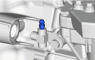
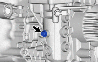
3. REMOVE RELEASE CYLINDER BLEEDER PLUG
| (a) Remove the release cylinder bleeder plug from the clutch release bleeder sub-assembly. |
|
4. REMOVE CLUTCH RELEASE BLEEDER SUB-ASSEMBLY
Click here

5. REMOVE CLUTCH RELEASE BEARING PLATE
Click here

6. REMOVE CLUTCH RELEASE CYLINDER WITH BEARING ASSEMBLY
Click here

7. REMOVE CLUTCH RELEASE CYLINDER TO BLEEDER TUBE
Click here

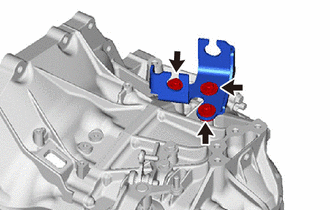
8. REMOVE CONTROL CABLE BRACKET
| (a) Remove the 3 bolts and control cable bracket from the manual transmission case. |
|
9. REMOVE SELECTING BELL CRANK ASSEMBLY
| (a) Remove the 2 bolts and selecting bell crank assembly from the manual transmission case. |
|
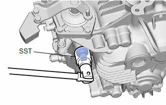
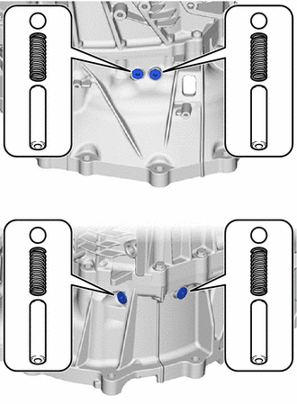
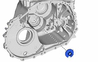
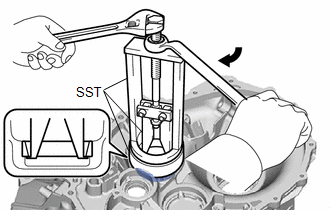
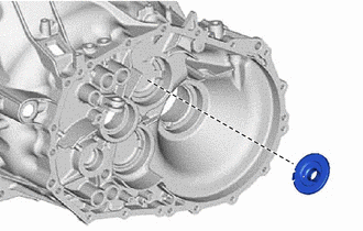
10. REMOVE BACK-UP LIGHT SWITCH ASSEMBLY
| (a) Using SST, remove the back-up light switch assembly and gasket from the manual transmission case. SST: 09816-30010 |
|
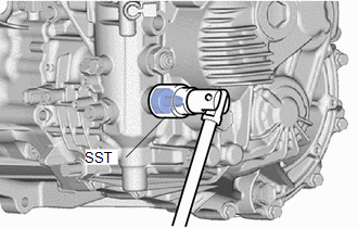
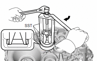
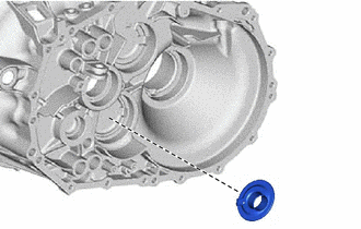
11. REMOVE NEUTRAL POSITION SWITCH
| (a) Using SST, remove the neutral position switch and gasket from the manual transmission case. SST: 09816-30010 |
|
12. REMOVE TEMPERATURE SENSOR
Click here

13. REMOVE TRANSMISSION REVOLUTION SENSOR
Click here

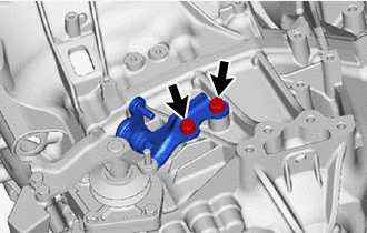
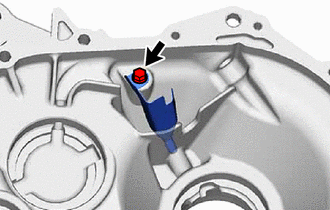
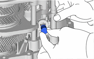
14. REMOVE NO. 1 LOCK BALL ASSEMBLY
| (a) Remove the No. 1 lock ball assembly from the manual transmission case. |
|
15. REMOVE NO. 2 LOCK BALL ASSEMBLY
| (a) Remove the No. 2 lock ball assembly from the manual transmission case. |
|
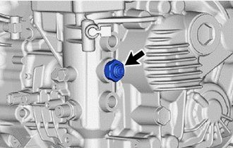
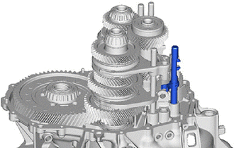
16. REMOVE SHIFT GATE PIN
| (a) Remove the shift gate pin from the manual transmission case. |
|
17. REMOVE SHIFT AND SELECT LEVER ASSEMBLY
| (a) Remove the 4 bolts and shift and select lever assembly from the manual transmission case. |
|
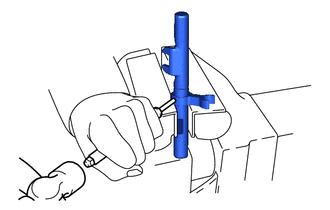
18. REMOVE SHIFT AND SELECT LEVER SHAFT STRAIGHT PIN
| (a) While pressing in the shift and select lever shaft straight pin as far as it will go, pull out the shift and select lever shaft straight pin to remove it. |
|
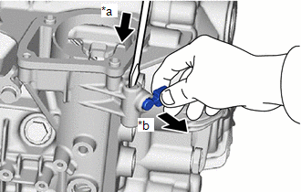
(b) Remove the spring.
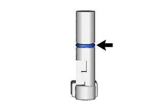
19. REMOVE SHIFT ARM PIVOT O-RING
| (a) Remove the O-ring from the shift and select lever shaft straight pin. |
|
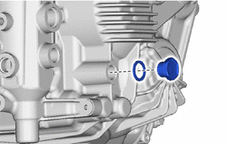
20. REMOVE MANUAL TRANSMISSION FILLER PLUG
| (a) Remove the manual transmission filler plug and gasket from the manual transmission case. |
|
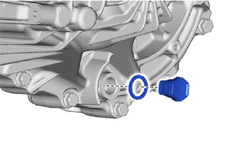
21. REMOVE MANUAL TRANSMISSION DRAIN PLUG
| (a) Remove the manual transmission drain plug and gasket from the manual transmission case. |
|
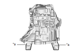
22. FIX MANUAL TRANSAXLE ASSEMBLY
| (a) Place the manual transaxle assembly on wooden blocks. |
|
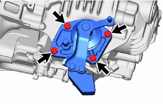
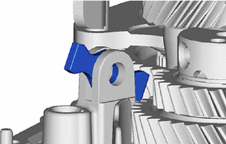
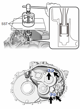
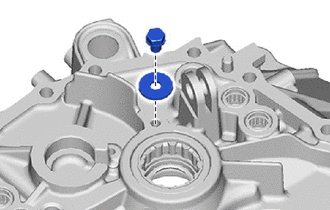
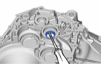
23. REMOVE SHIFT DETENT BALL
| (a) Using a 6 mm hexagon wrench, remove the 4 detent ball plugs from the front transaxle case. |
|
(b) Using a magnet hand, remove the 4 spring seats, 4 springs and 4 shift detent balls from the front transaxle case.
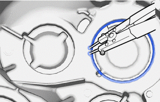
24. REMOVE REVERSE IDLER GEAR SHAFT BOLT
| (a) Remove the reverse idler gear shaft bolt and gasket from the manual transmission case. |
|
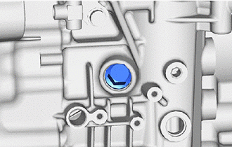
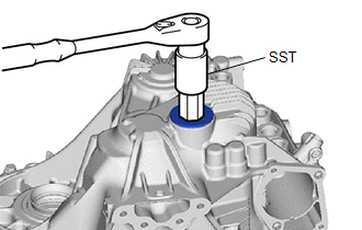
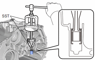
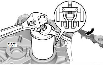
25. REMOVE MANUAL TRANSMISSION CASE PLUG
| (a) Using SST and 27 mm straight hexagon, remove the manual transmission case plugs from the manual transmission case. SST: 09816-30010 |
|
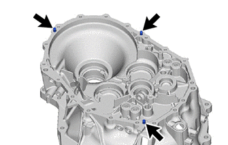
26. REMOVE MANUAL TRANSMISSION CASE
| (a) Remove the 8 bolts from the front transaxle case side. |
|
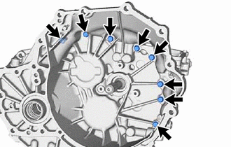
| (b) Remove the 10 bolts from the manual transmission case side. |
|
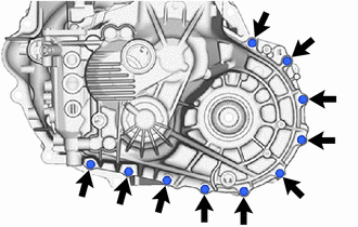
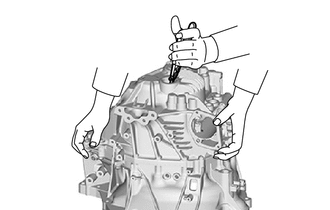
| (c) Using snap ring pliers, keep the snap ring stretched and remove the manual transmission case. |
|
27. REMOVE NO. 1 OIL RECEIVER PIPE
| (a) Remove the bolt and No. 1 receiver pipe from the manual transmission case. NOTICE: Do not damage the No. 1 oil receiver pipe. |
|
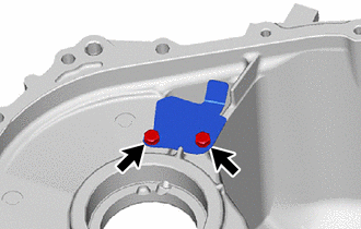
28. REMOVE TRANSMISSION OIL SEPARATOR
| (a) Remove the 2 bolts and transmission oil separator from the manual transmission case. |
|
29. REMOVE TRANSMISSION OIL SEPARATOR
| (a) Remove the 2 bolts and transmission oil separator from the front transaxle case. |
|
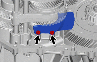
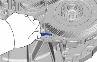
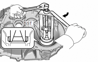
30. REMOVE 3RD AND 4TH SHIFT FORK SHAFT
| (a) Using a 5 mm pin punch and a hammer, tap out the slotted spring pin until the 3rd and 4th shift fork shaft becomes free. NOTICE:
|
|
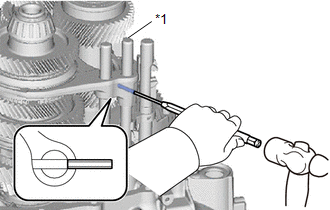
(b) Apply protective tape to the locations shown in the illustration.

| *1 | No. 2 Gear Shift Head |
 | Protective Tape |
(c) Using a 5 mm pin punch and a hammer, tap out the slotted spring pin until the 3rd and 4th shift fork shaft becomes free.
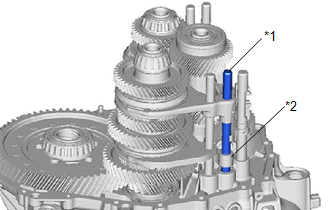
NOTICE:
- Do not allow the slotted spring pin to contact the No. 5 gear shift fork shaft.
- Do not fully extract the pin from the No. 2 gear shift head.
| (d) Remove the 3rd and 4th shift fork shaft and No. 2 gear shift head from the No. 2 gear shift fork and front transaxle case. |
|
(e) Remove the 2 slotted spring pins.
31. REMOVE NO. 5 GEAR SHIFT FORK SHAFT
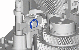
| (a) Using a screwdriver, remove the E-ring from the shift arm pivot. |
|
| (b) Remove the shift arm pivot from the shift arm. |
|
| (c) Remove the No. 5 gear shift fork shaft from the front transaxle case. |
|
| (d) Using a 5 mm pin punch and a hammer, remove the slotted spring pin from the No. 3 gear shift head. |
|
(e) Remove the No. 3 gear shift head from the No. 5 gear shift fork shaft.
32. REMOVE SHIFT ARM
| (a) Remove the shift arm from the front transaxle case. |
|
33. REMOVE REVERSE SHIFT FORK SHAFT
| (a) Remove the bolt from the reverse shift fork shaft. |
|
| (b) Remove the reverse shift fork shaft from the front transaxle case. |
|
34. INSPECT REVERSE IDLER GEAR THRUST CLEARANCE
Click here

35. INSPECT REVERSE IDLER GEAR RADIAL CLEARANCE
Click here

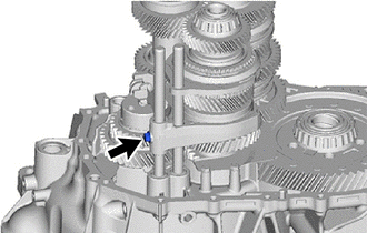
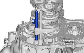
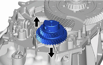
36. REMOVE REVERSE IDLER GEAR
| (a) Remove the reverse idler gear shaft by sliding and lifting it. |
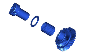
|
| (b) Remove the reverse idler gear, needle roller bearing and reverse idler thrust washer from the reverse idler gear shaft. |
|
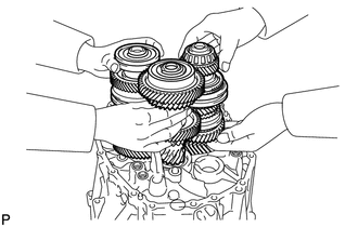
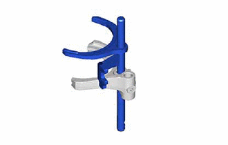
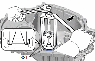
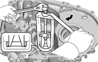
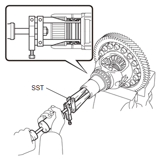
37. REMOVE INPUT SHAFT, NO. 1 OUTPUT SHAFT AND NO. 2 OUTPUT SHAFT
| (a) Bend left and right sides of SST in opposite directions. SST: 09312-52010 NOTICE: Do not bend SST more than necessary. |
|
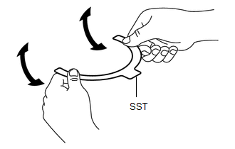
| (b) Install SST to the top and bottom of the No. 3 transmission hub sleeve. SST: 09312-52010 NOTICE: Make sure that SST does not easily come loose. HINT: Install SST in a tensioned state so that the No. 3 transmission hub sleeve does not shift out of position. |
|
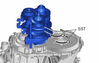
| (c) Remove the 3 shafts at the same time. |
|
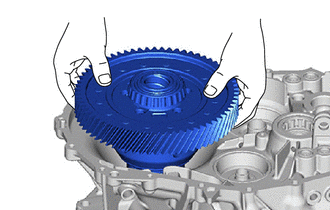
38. REMOVE DIFFERENTIAL GEAR ASSEMBLY
| (a) Remove the differential gear assembly from the front transaxle case. |
|
39. REMOVE TRANSMISSION MAGNET
| (a) Remove the transmission magnet from the front transaxle case. |
|
40. REMOVE NO. 1 GEAR SHIFT FORK
| (a) Remove the No. 1 gear shift fork from the No. 1 output shaft assembly. |
|
41. REMOVE NO. 2 GEAR SHIFT FORK
| (a) Remove the No. 2 gear shift fork from the No. 1 gear shift fork. |
|
42. REMOVE NO. 3 GEAR SHIFT FORK
| (a) Remove the No. 3 gear shift fork from the No. 2 output shaft assembly. |
|
43. REMOVE REVERSE SHIFT FORK
| (a) Remove the reverse shift fork from the No. 3 gear shift fork. |
|
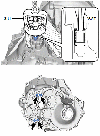
44. REMOVE OUTPUT SHAFT REAR BEARING
| (a) Using SST, remove the output shaft rear bearing outer race from the manual transmission case. SST: 09387-00041 SST: 09387-02020 |
|
45. REMOVE OUTPUT SHAFT REAR BEARING SHIM
| (a) Remove the output shaft rear bearing shim from the manual transmission case. |
|
46. REMOVE NO. 2 OUTPUT SHAFT REAR BEARING
| (a) Using SST, remove the No. 2 output shaft rear bearing outer race from the manual transmission case. SST: 09387-00041 SST: 09387-02020 |
|
47. REMOVE OUTPUT SHAFT REAR BEARING SHIM
| (a) Remove the output shaft rear bearing shim from the manual transmission case. |
|
48. REMOVE OUTPUT SHAFT COVER
| (a) Remove the output shaft cover from the manual transmission case. |
|
49. REMOVE SHIFT FORK SHAFT BEARING
| (a) Using SST, remove the 4 shift fork shaft bearings from the manual transmission case. SST: 09387-00041 09387-01021 SST: 09527-20011 SST: 09612-65014 |
|
50. REMOVE SHIFT AND SELECT LEVER SHAFT NEEDLE ROLLER BEARING
| (a) Using SST, remove the shift and select lever shaft needle roller bearing from the manual transmission case. SST: 09387-00041 09387-01021 SST: 09612-65014 |
|
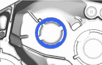
51. REMOVE INPUT SHAFT REAR BEARING SHAFT SNAP RING
| (a) Using snap ring pliers, remove the input shaft rear bearing shaft snap ring from the manual transmission case. |
|
52. REMOVE INPUT SHAFT FRONT BEARING
| (a) Remove the bolt and bearing lock plate from the front transaxle case. |
|
| (b) Using SST, remove the input shaft front bearing from the front transaxle case. SST: 09612-30012 |
|
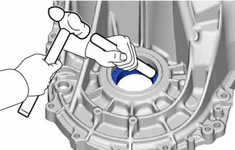
53. REMOVE FRONT TRANSAXLE CASE OIL SEAL
| (a) Using a screwdriver with its tip wrapped with protective tape, remove the front transaxle case oil seal from the front transaxle case. |
|
54. REMOVE OUTPUT SHAFT FRONT BEARING
| (a) Using SST, remove the output shaft front bearing from the front transaxle case. SST: 09387-00041 SST: 09387-02020 SST: 09527-17011 |
|
55. REMOVE OUTPUT SHAFT COVER
| (a) Remove the output shaft cover from the front transaxle case. |
|
56. REMOVE NO. 2 OUTPUT SHAFT FRONT BEARING
| (a) Using SST, remove the No. 2 output shaft front bearing outer race from the front transaxle case. SST: 09387-00041 SST: 09387-02020 SST: 09527-17011 |
|
57. REMOVE OUTPUT SHAFT COVER
| (a) Remove the output shaft cover from the front transaxle case. |
|
58. REMOVE MANUAL TRANSMISSION CASE STRAIGHT PIN
| (a) Remove the 3 manual transmission case straight pins from the front transaxle case. |
|
59. REMOVE SHIFT FORK SHAFT BEARING
| (a) Using SST, remove the 4 shift fork shaft bearings from the front transaxle case. SST: 09387-00041 09387-01021 SST: 09612-65014 |
|
60. REMOVE FRONT DRIVE SHAFT OIL SEAL LH
Click here

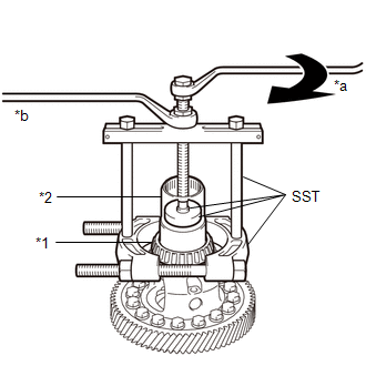
61. REMOVE FRONT DIFFERENTIAL CASE REAR TAPERED ROLLER BEARING
| (a) Using a brass bar and a hammer, remove the front differential case rear tapered roller bearing outer race and front differential case rear shim from the manual transmission case. |
|
| (b) Using SST, remove the front differential case rear tapered roller bearing from the front No. 1 differential case sub-assembly. SST: 09950-00020 SST: 09950-00030 SST: 09950-40011 09957-04010 SST: 09950-60011 09951-00540 |
|
62. REMOVE TRANSAXLE CASE OIL SEAL
Click here

63. REMOVE FRONT DRIVE SHAFT OIL SEAL RH
| (a) Using SST, remove the front drive shaft oil seal RH from the transmission sleeve yoke. SST: 09308-00010 NOTICE: Be careful not to damage the transmission sleeve yoke. |
|
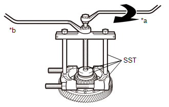
64. REMOVE FRONT DIFFERENTIAL CASE FRONT TAPERED ROLLER BEARING
| (a) Using SST, remove the front differential case front tapered roller bearing outer race from the front transaxle case. SST: 09387-00041 SST: 09387-02020 SST: 09527-17011 |
|
| (b) Using SST, remove the front differential case front tapered roller bearing and transmission sleeve yoke from the front No. 1 differential case sub-assembly. SST: 09950-00020 SST: 09950-00030 SST: 09950-40011 09957-04010 SST: 09950-60011 09951-00410 |
|
 Components
COMPONENTS ILLUSTRATION
*1 SHIFT GATE PIN *2 NO. 2 LOCK BALL ASSEMBLY *3 NO. 1 LOCK BALL ASSEMBLY *4 TRANSMISSION REVOLUTION SENSOR *5 TEMPERATURE SENSOR *6 NEUTRAL POSITION SWITCH *7 BACK-UP LAMP SWITCH ASSEMBLY *8 SELECTING BELL CRANK ASSEMBLY *9 CONTROL CABLE BRACKET *10 CLUTCH RELEASE CYLINDER WITH BEARING ASSEMBLY *11 CLUTCH TUBE BOOT *12 BLEEDER CLUTCH RELEASE TUBE *13 CLUTCH RELEASE BLEEDER SUB-ASSEMBLY *14 CLUTCH RELEASE BEARING PLATE *15 RELEASE CYLINDER BLEEDER PLUG *16 RELEASE CYLINDER BLEEDER PLUG CAP *17 NO...
 Inspection
INSPECTION PROCEDURE 1. INSPECT REVERSE IDLER GEAR THRUST CLEARANCE (a) Using a feeler gauge, measure the reverse idler gear thrust clearance. Standard Clearance: 0...
Other information:
Toyota Yaris XP210 (2020-2026) Reapir and Service Manual: Removal
REMOVAL CAUTION / NOTICE / HINT HINT: Use the same procedure for the RH side and LH side. The following procedure is for the LH side. PROCEDURE 1. REMOVE WINDSHIELD OUTSIDE MOULDING (a) Apply protective tape around the windshield outside moulding...
Toyota Yaris XP210 (2020-2026) Reapir and Service Manual: Glass Position Initialization Incomplete (B2313)
DESCRIPTION The power window regulator motor assemblies are operated by the multiplex network master switch assembly or power window regulator switch assembly. The power window regulator motor assemblies have motor, regulator and ECU functions. When the ECU built into a power window regulator motor assembly determines that the power window regulator motor assemblies have not been initialized, DTC B2313 is stored...
Categories
- Manuals Home
- Toyota Yaris Owners Manual
- Toyota Yaris Service Manual
- Fuel Gauge
- Maintenance
- How to connect USB port/Auxiliary jack
- New on site
- Most important about car
Fuel Gauge
The fuel gauge shows approximately how much fuel is remaining in the tank when the ignition is switched ON. We recommend keeping the tank over 1/4 full.
