Toyota Yaris: Front Door / Disassembly
DISASSEMBLY
CAUTION / NOTICE / HINT
The necessary procedures (adjustment, calibration, initialization, or registration) that must be performed after parts are removed and installed, or replaced during the front door removal/installation are shown below.
Necessary Procedure After Parts Removed/Installed/Replaced| Replaced Part or Performed Procedure | Necessary Procedure | Effect/Inoperative Function when Necessary Procedure not Performed | Link |
|---|---|---|---|
| Initialize power window control system |
|
|
HINT:
-
When the cable is disconnected/reconnected to the auxiliary battery terminal, systems temporarily stop operating. However, each system has a function that completes learning the first time the system is used.
-
Learning completes when vehicle is driven
Effect/Inoperative Function When Necessary Procedures are not Performed
Necessary Procedures
Link
Lane tracing assist system
Drive the vehicle straight ahead at 35 km/h (22 mph) or more for 5 seconds or more.
.gif)
Pre-collision system
Stop and start system
Drive the vehicle until stop and start control is permitted (approximately 5 to 60 minutes)
-
Learning completes when vehicle is operated normally
Effect/Inoperative Function When Necessary Procedures are not Performed
Necessary Procedures
Link
Power door lock control system
- Back door opener
Perform door unlock operation with door control switch or electrical key transmitter sub-assembly switch.
Air conditioning system
After the power switch is turned to on (IG), the servo motor standard position is recognized.
-
-
Learning completes when vehicle is driven
- Use the same procedure for the LH side and RH side.
- The following procedure is for the LH side.
PROCEDURE
1. PRECAUTION
CAUTION:
Be sure to read Precaution thoroughly before servicing.
Click here
NOTICE:
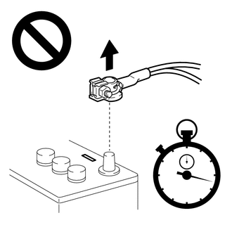
After turning the ignition switch off, waiting time may be required before disconnecting the cable from the negative (-) auxiliary battery terminal.
Click here
2. CABLE FROM NEGATIVE AUXILIARY BATTERY TERMINAL
Click here
CAUTION:
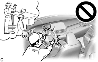
- Wait at least 90 seconds after disconnecting the cable from the negative (-) auxiliary battery terminal to disable the SRS system.
- If the airbag deploys for any reason, it may cause a serious accident.
3. REMOVE FRONT DOOR LOWER FRAME BRACKET GARNISH
| (a) Disengage the claws and clip to remove the front door lower frame bracket garnish. |
|
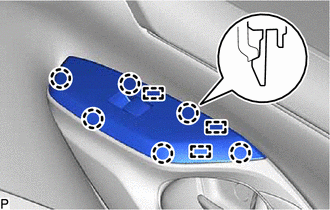
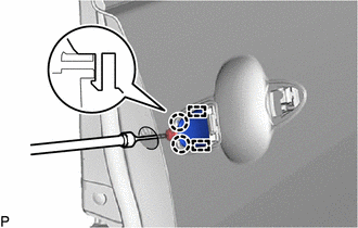
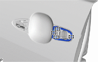
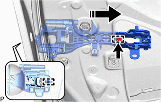
4. REMOVE MULTIPLEX NETWORK MASTER SWITCH ASSEMBLY WITH FRONT ARMREST BASE UPPER PANEL (for Driver Side)
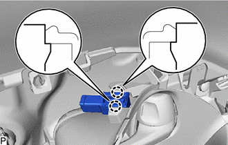
| (a) Disengage the claws and guides. |
|
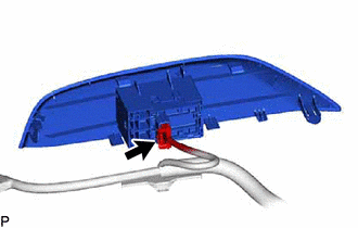
| (b) Disconnect the 2 connectors to remove the multiplex network master switch assembly with front armrest base upper panel. |
|
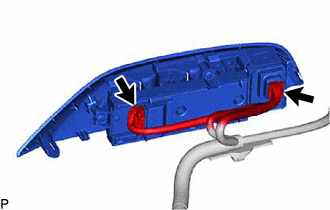
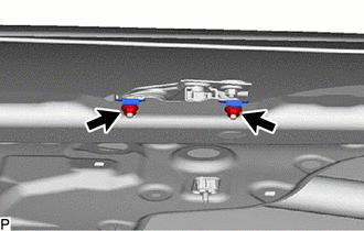
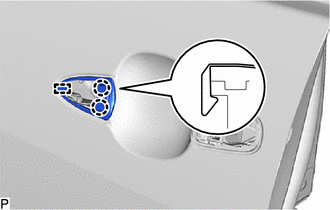
5. REMOVE POWER WINDOW REGULATOR SWITCH ASSEMBLY WITH FRONT ARMREST BASE UPPER PANEL (for Front Passenger Side)
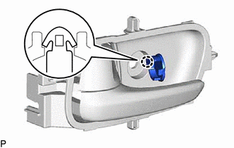
| (a) Disengage the claws and guides. |
|
| (b) Disconnect the connector to remove the power window regulator switch assembly with front armrest base upper panel. |
|
6. REMOVE FRONT DOOR TRIM GARNISH
(a) Remove the screw.
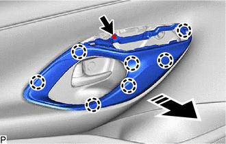
.png) | Remove in this Direction |
(b) Disengage the claws to remove the front door trim garnish as shown in the illustration.
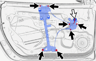
7. REMOVE FRONT DOOR TRIM BOARD SUB-ASSEMBLY
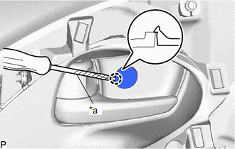
| (a) Using a screwdriver with its tip wrapped in protective tape, disengage the claw to open the front door inside handle bezel plug. |
|
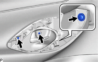
| (b) Remove the 3 screws. |
|
(c) Disengage the clips as shown in the illustration.
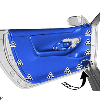
 | Place Hands Here |
|
| Remove in this Direction |
(d) Disengage the front door trim board sub-assembly with the front door glass inner weatherstrip, front door vent seal and front door panel protector as shown in the illustration.
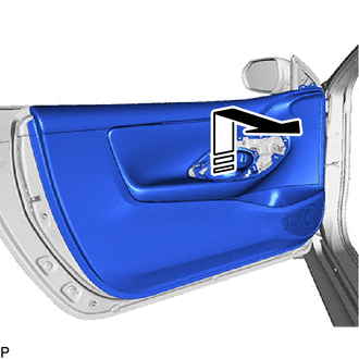
|
| Remove in this Direction |
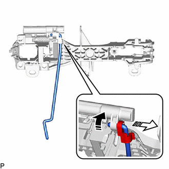
(e) Disengage the guides to disconnect the front door lock/unlock knob inside locking cable and front door lock open lever remote control cable to remove the front door trim board sub-assembly as shown in the illustration.
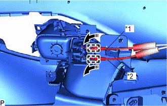
| *1 | Front Door Lock/Unlock Knob Inside Locking Cable |
| *2 | Front Door Lock Open Lever Remote Control Cable |
|
| Remove in this Direction |
8. REMOVE NO. 1 INTERIOR ILLUMINATION LIGHT ASSEMBLY (w/ Interior Illumination)
| (a) Disengage the claws to remove the No. 1 interior illumination light assembly |
|
9. REMOVE FRONT DOOR INSIDE HANDLE SUB-ASSEMBLY
| (a) Disengage the guides to remove the front door inside handle sub-assembly. |
|

10. REMOVE FRONT DOOR INSIDE HANDLE BEZEL PLUG
| (a) Disengage the claw to remove front door inside handle bezel plug. |
|
11. REMOVE FRONT DOOR GLASS INNER WEATHERSTRIP
(a) Disengage the claws to remove the front door glass inner weatherstrip as shown in the illustration.
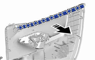
|
| Remove in this Direction |
12. REMOVE NO. 1 FRONT SPEAKER ASSEMBLY
Click here
13. REMOVE NO. 1 FRONT SPEAKER BRACKET
| (a) Disengage the guide. |
|
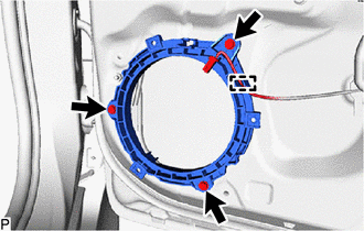
(b) Remove the 3 screws and No. 1 front speaker bracket.
14. REMOVE OUTER REAR VIEW MIRROR ASSEMBLY
Click here
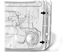
15. REMOVE FRONT DOOR SERVICE HOLE COVER
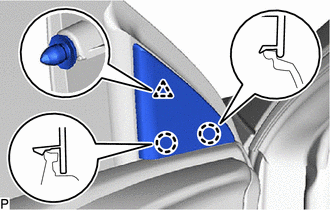
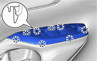
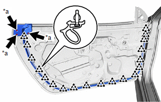
| (a) Turn the 3 front door service hole cover clips 45° to remove it clips as shown in the illustration. |
|
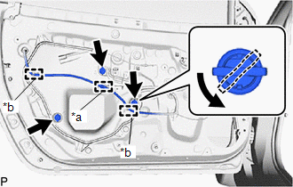
(b) Disengage the guides and clamp to separate the wire harness from the front door service hole cover.
| (c) Disengage the clips to remove the front door service hole cover. |
|
16. REMOVE SIDE AIRBAG PRESSURE SENSOR
Click here
17. REMOVE HOLE PLUG
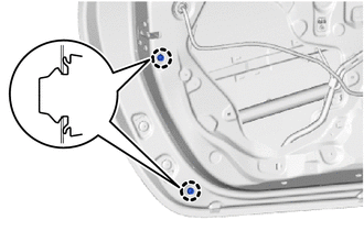
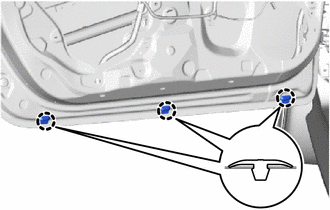
| (a) Remove the 4 hole plugs. |
|
18. REMOVE WINDOW REGULATOR SHIM
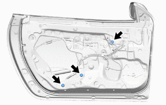
| (a) Loosen the 2 nut. |
|
(b) Remove the 2 window regulator shims.
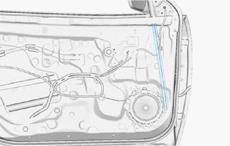
19. REMOVE FRONT DOOR GLASS SUB-ASSEMBLY
(a) for Driver Side:
(1) Connect the multiplex network master switch assembly.
(2) Connect the cable to the negative (-) auxiliary battery terminal.
(3) Move the front door glass sub-assembly so that the door glass bolts can be seen.
(4) Disconnect the cable from the negative (-) auxiliary battery terminal.
(5) Disconnect the multiplex network master switch assembly.
(b) for Front Passenger Side:
(1) Connect the power window regulator switch assembly.
(2) Connect the cable to the negative (-) auxiliary battery terminal.
(3) Move the front door glass sub-assembly so that the door glass bolts can be seen.
(4) Disconnect the cable from the negative (-) auxiliary battery terminal.
(5) Disconnect the power window regulator switch assembly.
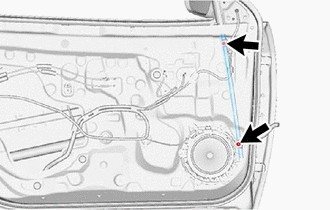
| (c) Remove the 3 nuts. |
|
(d) Remove the front door glass sub-assembly as shown in the illustration.
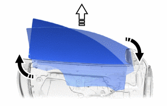
|
| Remove in this Direction (1) |
 | Remove in this Direction (2) |
NOTICE:
Do not damage the front door glass sub-assembly.
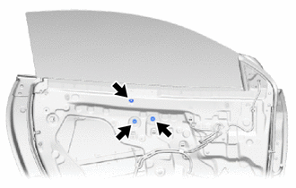
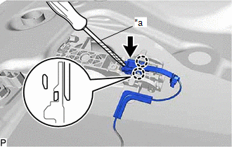
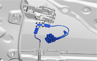
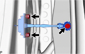
20. REMOVE FRONT DOOR WINDOW REGULATOR ASSEMBLY
(a) Disconnect the connector.
.png) | Nut |
 | Connector |
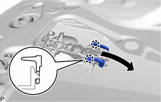
(b) Remove the 7 nuts and front door window regulator assembly.
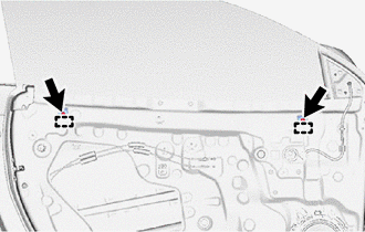
21. REMOVE HOLE SEAL
| (a) Remove the 2 hole seals. |
|
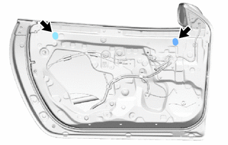
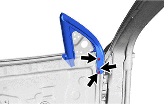
22. REMOVE FRONT DOOR UPPER WINDOW STOP
| (a) Remove the 2 bolts. |
|
(b) Disengage the guides to remove the 2 front door upper window stops.
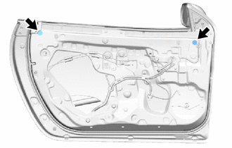
23. REMOVE HOLE SEAL
| (a) Remove the 2 hole seals. |
|
24. REMOVE DOOR GLASS FEMALE STABILIZER
| (a) Remove the bolt. |
|
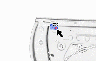
(b) Disengage the guide to remove the door glass female stabilizer.
25. REMOVE FRONT DOOR GLASS RUN
| (a) Remove the front door glass run. |
|
26. REMOVE FRONT DOOR FRONT LOWER FRAME SUB-ASSEMBLY
| (a) Remove the bolt, nut and front door front lower frame sub-assembly. |
|
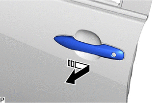
27. REMOVE FRONT DOOR OUTSIDE HANDLE ASSEMBLY
(a) w/ Entry and Start System:
| (1) Disengage the claws. |
|
(2) Using a screwdriver with its tip wrapped in protective tape, disconnect the connector.
| (b) Disengage the 2 claws and move the lever as shown in the illustration. |
|
(c) Remove the front door outside handle assembly as shown in the illustration.
|
| Remove in this Direction |
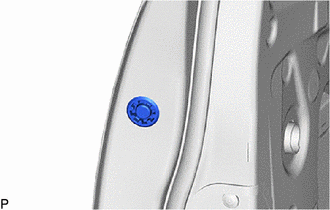
28. REMOVE FRONT DOOR LOCK CYLINDER ASSEMBLY (for Driver Side)
| (a) Remove the hole plug. |
|
| (b) Using a T30 "TORX" socket wrench, loosen the screw. |
|
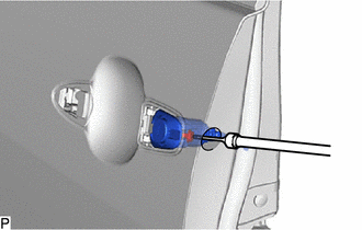
(c) Remove the front door lock cylinder assembly.
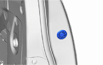
29. REMOVE FRONT DOOR OUTSIDE HANDLE COVER (for Front Passenger Side)
| (a) Remove the hole plug. |
|
| (b) Using a T30 "TORX" socket wrench, loosen the screw. |
|
(c) Disengage the claws and guides to remove the front door outside handle cover.
30. REMOVE FRONT DOOR OUTSIDE HANDLE FRONT PAD
| (a) Disengage the claws and guide to remove the front door front outside handle pad. |
|
31. REMOVE FRONT DOOR OUTSIDE HANDLE REAR PAD
| (a) Disengage the guides to remove the front door outside handle rear pad. |
|
32. REMOVE FRONT DOOR WITH MOTOR LOCK ASSEMBLY
Click here
33. REMOVE FRONT DOOR OUTSIDE HANDLE FRAME SUB-ASSEMBLY
(a) w/ Entry and Start System:
| (1) Disengage the clamp to separate the wire harness. |
|
(b) Using a T30 "TORX" socket wrench, loosen the screw.
|
| Remove in this Direction |
(c) Disengage the guides to remove the front door outside handle frame sub-assembly as shown in the illustration.
34. REMOVE FRONT DOOR LOCK OPEN ROD
(a) Disengage the snap to remove the front door lock open rod from the front door outside frame sub-assembly as shown in the illustration.
|
| Remove in this Direction (1) |
|
| Remove in this Direction (2) |
35. REMOVE FRONT DOOR GLASS OUTER WEATHERSTRIP ASSEMBLY
Click here
36. REMOVE FRONT DOOR CHECK ASSEMBLY
| (a) Remove the 3 bolts and front door check assembly. |
|
37. REMOVE FRONT DOOR DIVISION BAR SEAL
| (a) Remove the 3 clips. |
|
(b) Remove the front door division bar seal.
38. REMOVE FRONT DOOR WEATHERSTRIP
| (a) Disengage the 3 clips (A) and other clips to remove the front door weatherstrip. |
|
39. REMOVE CUSHION
| (a) Disengage the claws to remove the 2 cushions. |
|
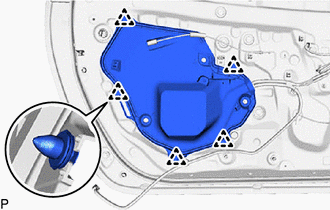
40. REMOVE FRONT DOOR DUST PROOF SEAL
| (a) Disengage the claws to remove the 3 front door dust proof seals. |
|
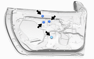
41. REMOVE HOLE PLUG
| (a) Remove the 3 hole plugs. |
|
42. REMOVE HOLE PLUG
| (a) Remove the 2 hole plugs. |
|
 Components
COMPONENTS ILLUSTRATION
*A for Front Passenger Side *B for Driver Side *C w/ Interior Illumination - - *1 FRONT DOOR LOWER FRAME BRACKET GARNISH *2 MULTIPLEX NETWORK MASTER SWITCH ASSEMBLY WITH FRONT ARMREST BASE UPPER PANEL *3 POWER WINDOW REGULATOR SWITCH ASSEMBLY WITH FRONT ARMREST BASE UPPER PANEL *4 FRONT DOOR TRIM GARNISH *5 FRONT DOOR TRIM BOARD SUB-ASSEMBLY *6 FRONT DOOR INSIDE HANDLE SUB-ASSEMBLY *7 FRONT DOOR INSIDE HANDLE BEZEL PLUG *8 FRONT DOOR GLASS INNER WEATHERSTRIP *9 NO...
 Adjustment
ADJUSTMENT CAUTION / NOTICE / HINT
*a Centering Bolt *b Standard Bolt HINT:
Use the same procedure for the LH side and RH side.
The following procedure is for the LH side...
Other information:
Toyota Yaris XP210 (2020-2026) Reapir and Service Manual: Roof Drip Side Moulding
ComponentsCOMPONENTS ILLUSTRATION *1 ROOF SIDE RAIL WEATHERSTRIP *2 ROOF SIDE RAIL WEATHERSTRIP RETAINER RemovalREMOVAL CAUTION / NOTICE / HINT HINT: Use the same procedure for the RH and LH sides. The procedure listed below is for the LH side...
Toyota Yaris XP210 (2020-2026) Reapir and Service Manual: Inspection
INSPECTION PROCEDURE 1. INSPECT PROPELLER SHAFT WITH CENTER BEARING ASSEMBLY (a) Using a dial indicator, measure the propeller shaft runout for the front side. Maximum Runout: 0.4 mm (0.0157 in.) If the runout is more than the maximum, replace the propeller shaft with center bearing assembly...
Categories
- Manuals Home
- Toyota Yaris Owners Manual
- Toyota Yaris Service Manual
- Removal
- Immobilizer System
- Engine Start Function When Key Battery is Dead
- New on site
- Most important about car
Fuel-Filler Lid and Cap
WARNING
When removing the fuel-filler cap, loosen the cap slightly and wait for any hissing to stop, then remove it
Fuel spray is dangerous. Fuel can burn skin and eyes and cause illness if ingested. Fuel spray is released when there is pressure in the fuel tank and the fuel-filler cap is removed too quickly.