Toyota Yaris: Front Door / Adjustment
ADJUSTMENT
CAUTION / NOTICE / HINT
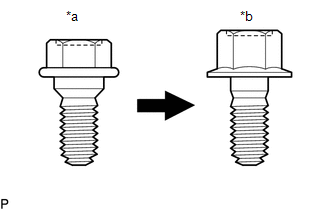
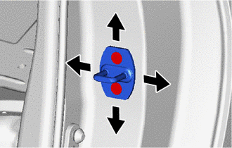
| *a | Centering Bolt |
| *b | Standard Bolt |
HINT:
- Use the same procedure for the LH side and RH side.
- The following procedure is for the LH side.
- Centering bolts are used to install the door hinges to the vehicle body and door. The door cannot be adjusted with the centering bolts installed. Substitute the centering bolts with standard bolts when making adjustments.
-
The specified torque for standard bolts is shown in the standard bolt chart.
Click here
.gif)
PROCEDURE
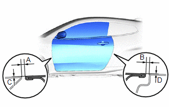
1. INSPECT FRONT DOOR PANEL SUB-ASSEMBLY
| (a) Check that the clearance measurements of areas "A" to "D" are within the standard ranges. Standard Clearance:
|
|
2. ADJUST FRONT DOOR PANEL SUB-ASSEMBLY
| (a) Using SST, loosen the 4 hinge bolts on the vehicle body and adjust the door position. SST: 09812-00010 |
|
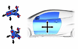
(b) Tighten the 4 hinge bolts on the vehicle body after adjustment.
Torque:
26 N·m {265 kgf·cm, 19 ft·lbf}
| (c) Loosen the 4 hinge bolts on the door and adjust the door position. |
|
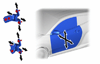
(d) Tighten the 4 hinge bolts on the door after adjustment.
Torque:
21 N·m {214 kgf·cm, 15 ft·lbf}
| (e) Using a T40 "TORX" socket wrench, slightly loosen the 2 striker mounting screws. |
|
(f) Using a brass bar and a hammer, hit the striker to adjust its position.
(g) Using a T40 "TORX" socket wrench, tighten the 2 striker mounting screws after adjustment.
Torque:
23 N·m {235 kgf·cm, 17 ft·lbf}
 Disassembly
DISASSEMBLY CAUTION / NOTICE / HINT The necessary procedures (adjustment, calibration, initialization, or registration) that must be performed after parts are removed and installed, or replaced during the front door removal/installation are shown below...
 Reassembly
REASSEMBLY CAUTION / NOTICE / HINT HINT:
Use the same procedure for the LH side and RH side.
The following procedure is for the LH side.
PROCEDURE 1...
Other information:
Toyota Yaris XP210 (2020-2026) Reapir and Service Manual: Vehicle Speed Signal Circuit Open (B228231,B228262)
DESCRIPTION DTC B228231 is stored when the vehicle speed signal sent by the combination meter assembly via direct line and the vehicle speed signal sent via CAN communication do not match. DTC B228262 is stored when a malfunction in the vehicle speed sensor is detected...
Toyota Yaris XP210 (2020-2026) Reapir and Service Manual: Remote Up / Down Function does not Operate
DESCRIPTION When the ignition switch is ON, the multiplex network master switch assembly sends remote up and down signals to each door window regulator motor assembly via LIN communication. WIRING DIAGRAM CAUTION / NOTICE / HINT NOTICE: The power window control system uses the LIN communication system...
Categories
- Manuals Home
- Toyota Yaris Owners Manual
- Toyota Yaris Service Manual
- Brake System Control Module "A" System Voltage System Voltage Low (C137BA2)
- Immobilizer System
- Fuse Panel Description
- New on site
- Most important about car
Fuel Gauge
The fuel gauge shows approximately how much fuel is remaining in the tank when the ignition is switched ON. We recommend keeping the tank over 1/4 full.
