Toyota Yaris: Input Shaft / Reassembly
REASSEMBLY
PROCEDURE
1. INSTALL INPUT SHAFT FRONT BEARING INNER RACE
| (a) Using SST and a press, install the input shaft front bearing inner race to the input shaft. SST: 09608-00071 |
|
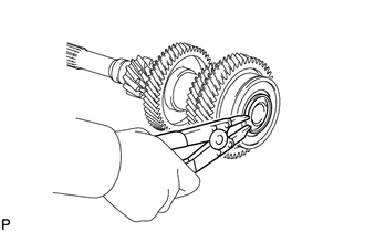
2. INSTALL INPUT SHAFT SNAP RING
| (a) Using a brass bar and hammer, tap a new input shaft snap ring to the input shaft. |
|
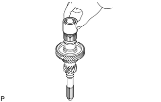
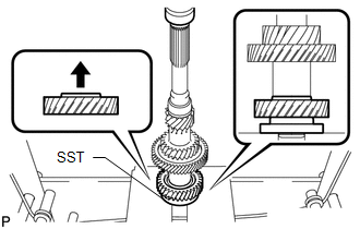
3. INSTALL 4TH DRIVE GEAR
| (a) Using SST and a press, install the 4th drive gear to the input shaft. SST: 09309-14040 |
|
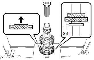
4. INSTALL 3RD DRIVE GEAR
| (a) Install the spacer to the input shaft. |
|
| (b) Using SST and a press, install the 3rd drive gear to the input shaft. SST: 09309-14040 |
|
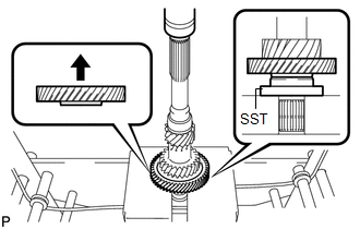
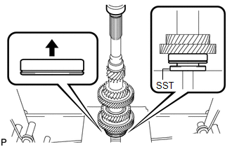
5. INSTALL 6TH DRIVE GEAR
| (a) Using SST and a press, install the 6th drive gear to the input shaft. SST: 09309-14040 |
|
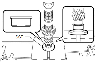
6. INSTALL INPUT SHAFT REAR RADIAL BALL BEARING
| (a) Using SST and a press, install the input shaft rear radial ball bearing to the input shaft. SST: 09506-30012 |
|
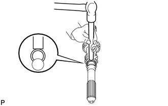
7. INSTALL INPUT SHAFT REAR BEARING SHAFT SNAP RING
| (a) Select a new input shaft rear bearing shaft snap ring, using the table below, that makes the thrust clearance of the input shaft bearing less than 0.1 mm (0.00394 in.). Input Shaft Rear Bearing Shaft Snap Ring Thickness:
|
|
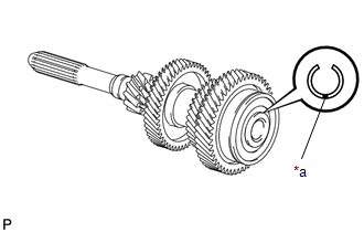
| (b) Using a snap ring expander, install the input shaft rear bearing shaft snap ring to the input shaft. |
|
 Inspection
INSPECTION PROCEDURE 1. INSPECT INPUT SHAFT (a) Check the input shaft for wear and damage.
(b) Using a dial indicator, measure the input shaft runout...
 Intelligent Manual Transmission Switch
ComponentsCOMPONENTS ILLUSTRATION
*1 INTELLIGENT MANUAL TRANSMISSION SWITCH (COMBINATION SWITCH ASSEMBLY) - - InspectionINSPECTION PROCEDURE 1...
Other information:
Toyota Yaris XP210 (2020-2026) Reapir and Service Manual: On-vehicle Inspection
ON-VEHICLE INSPECTION PROCEDURE 1. INSPECT BRAKE FLUID LEVEL IN RESERVOIR (a) Check the fluid level. HINT: If the brake fluid level is lower than the MIN line, inspect for brake fluid leaks and brake pad wear. If necessary, refill the reservoir with brake fluid to the MAX line after repair or replacement...
Toyota Yaris XP210 (2020-2026) Reapir and Service Manual: Removal
REMOVAL CAUTION / NOTICE / HINT The necessary procedures (adjustment, calibration, initialization or registration) that must be performed after parts are removed, installed or replaced during the No. 1 side airbag sensor removal/installation are shown below...
Categories
- Manuals Home
- Toyota Yaris Owners Manual
- Toyota Yaris Service Manual
- Fuse Panel Description
- Key Battery Replacement
- Adjustment
- New on site
- Most important about car
Refueling
Before refueling, close all the doors, windows, and the liftgate/trunk lid, and switch the ignition OFF.
To open the fuel-filler lid, pull the remote fuel-filler lid release.
