Toyota Yaris: Front Door Speaker / Removal
REMOVAL
CAUTION / NOTICE / HINT
HINT:
- Use the same procedure for the RH and LH sides.
- The procedure listed below is for the LH side.
PROCEDURE
1. REMOVE FRONT DOOR LOWER FRAME BRACKET GARNISH
Click here

2. REMOVE MULTIPLEX NETWORK MASTER SWITCH ASSEMBLY WITH FRONT ARMREST BASE UPPER PANEL (for Driver Side)
Click here

3. REMOVE POWER WINDOW REGULATOR SWITCH ASSEMBLY WITH FRONT ARMREST BASE UPPER PANEL (for Front Passenger Side)
Click here

4. REMOVE FRONT DOOR TRIM GARNISH
Click here

5. REMOVE FRONT DOOR TRIM BOARD SUB-ASSEMBLY
Click here

6. REMOVE FRONT DOOR GLASS INNER WEATHERSTRIP
Click here

7. REMOVE FRONT NO. 1 SPEAKER ASSEMBLY
| (a) Disconnect the connector. |
|
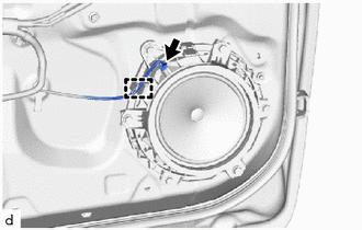
(b) Disengage the clamp.
| (c) Remove the 3 screws. |
|
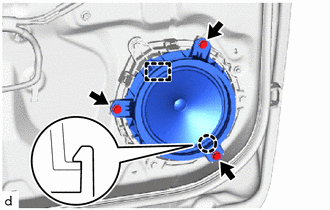
(d) Disengage the claw and hook to remove the front No. 1 speaker assembly.
8. REMOVE FRONT NO. 1 SPEAKER BRACKET
| (a) Remove the 3 screws. |
|
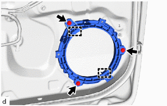
(b) Disengage the hooks to remove the front No. 1 speaker bracket.
 Components
COMPONENTS ILLUSTRATION
*A for Front Passenger Side *B for Driver Side *1 FRONT DOOR LOWER FRAME BRACKET GARNISH *2 MULTIPLEX NETWORK MASTER SWITCH ASSEMBLY WITH FRONT ARMREST BASE UPPER PANEL *3 POWER WINDOW REGULATOR SWITCH ASSEMBLY WITH FRONT ARMREST BASE UPPER PANEL *4 FRONT DOOR TRIM GARNISH *5 FRONT DOOR TRIM BOARD SUB-ASSEMBLY *6 FRONT DOOR GLASS INNER WEATHERSTRIP *7 FRONT NO...
 Inspection
INSPECTION PROCEDURE 1. INSPECT FRONT NO. 1 SPEAKER ASSEMBLY (for RH Side) (a) Check the resistance. (1) Measure the resistance according to the value(s) in the table below...
Other information:
Toyota Yaris XP210 (2020-2026) Reapir and Service Manual: Brake Pressure Sensor "A" Circuit Voltage Above Threshold (C054017)
DESCRIPTION DTC No. Detection Item DTC Detection Condition Trouble Area DTC Output from C054017 Brake Pressure Sensor "A" Circuit Voltage Above Threshold When vehicle speed exceeds 3 km/h (2 mph) and stop light switch assembly is OFF, master cylinder pressure continuously exceeds 1...
Toyota Yaris XP210 (2020-2026) Reapir and Service Manual: Reassembly
REASSEMBLY PROCEDURE 1. INSTALL BACK DOOR DUST PROOF SEAL (a) Engage the claw to install 3 new back door dust proof seals. 2. INSTALL NO. 2 BACK DOOR WIRE (a) Engage the clamps to install the No. 2 back door wire. (b) Connect the 3 connectors...
Categories
- Manuals Home
- Toyota Yaris Owners Manual
- Toyota Yaris Service Manual
- To Set Speed
- Battery Monitor Module General Electrical Failure (P058A01)
- Diagnostic Trouble Code Chart
- New on site
- Most important about car
Supplemental Restraint System (SRS) Precautions
The front and side supplemental restraint systems (SRS) include different types of air bags. Please verify the different types of air bags which are equipped on your vehicle by locating the “SRS AIRBAG” location indicators. These indicators are visible in the area where the air bags are installed.
The air bags are installed in the following locations:
The steering wheel hub (driver air bag) The front passenger dashboard (front passenger air bag) The outboard sides of the front seatbacks (side air bags) The front and rear window pillars, and the roof edge along both sides (curtain air bags)