Toyota Yaris: Ea67f (manual Transmission / Transaxle) / Intelligent Manual Transmission Switch
Components
COMPONENTS
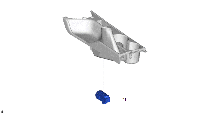
ILLUSTRATION

| *1 | INTELLIGENT MANUAL TRANSMISSION SWITCH (COMBINATION SWITCH ASSEMBLY) | - | - |
Inspection
INSPECTION
PROCEDURE
1. INSPECT INTELLIGENT MANUAL TRANSMISSION SWITCH (COMBINATION SWITCH ASSEMBLY)
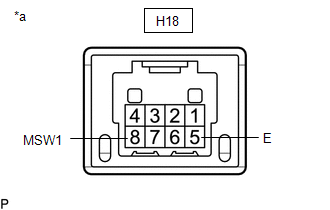
(a) Check the resistance.
| (1) Measure the resistance according to the value(s) in the table below. Standard Resistance:
If the result is not as specified, replace the intelligent manual transmission switch (combination switch assembly). |
|
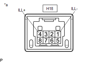
(b) Check that the illumination illuminates.
| (1) Apply auxiliary battery voltage between the terminals of the switch, and check the illumination condition of the intelligent manual transmission switch (combination switch assembly). OK:
If the result is not as specified, replace the intelligent manual transmission switch (combination switch assembly). |
|
 Reassembly
REASSEMBLY PROCEDURE 1. INSTALL INPUT SHAFT FRONT BEARING INNER RACE (a) Using SST and a press, install the input shaft front bearing inner race to the input shaft...
Other information:
Toyota Yaris XP210 (2020-2026) Owner's Manual: Bluetooth® Audio
Applicable Bluetooth® specification (Recommended)Ver. 1.1/1.2/2.0 + EDR/2.1 + EDR/3.0 (conformity) Response profile A2DP (Advanced Audio Distribution Profile) Ver. 1.0/1.2 AVRCP (Audio/Video Remote Control Profile) Ver. 1.0/1.3/1.4 A2DP is a profile which transmits only audio to the Bluetooth® unit...
Toyota Yaris XP210 (2020-2026) Reapir and Service Manual: Manual Transaxle Oil
ComponentsCOMPONENTS ILLUSTRATION *1 NO. 1 ENGINE UNDER COVER ASSEMBLY *2 ENGINE UNDER COVER LH *3 MANUAL TRANSMISSION FILLER PLUG *4 MANUAL TRANSMISSION DRAIN PLUG *5 GASKET - - N*m (kgf*cm, ft.*lbf): Specified torque ● Non-reusable part On-vehicle InspectionON-VEHICLE INSPECTION PROCEDURE 1...
Categories
- Manuals Home
- Toyota Yaris Owners Manual
- Toyota Yaris Service Manual
- Brake System Control Module "A" System Voltage System Voltage Low (C137BA2)
- Power Integration No.1 System Missing Message (B235287,B235587,B235787-B235987)
- Opening and Closing the Liftgate/Trunk Lid
- New on site
- Most important about car
Key Suspend Function
If a key is left in the vehicle, the functions of the key left in the vehicle are temporarily suspended to prevent theft of the vehicle.
To restore the functions, press the unlock button on the functions-suspended key in the vehicle.


