Toyota Yaris: Front Door / Reassembly
REASSEMBLY
CAUTION / NOTICE / HINT
HINT:
- Use the same procedure for the LH side and RH side.
- The following procedure is for the LH side.
PROCEDURE
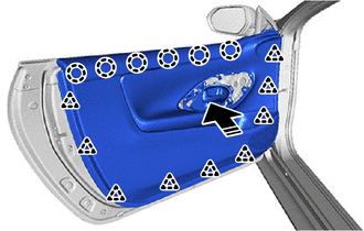
1. INSTALL HOLE PLUG
| (a) Install the 2 hole plugs. |
|
.png)
2. INSTALL HOLE PLUG
| (a) Install the 3 hole plugs. |
|
.png)
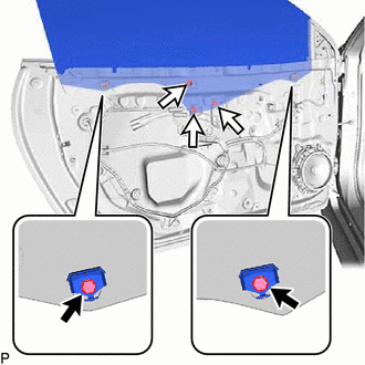
3. INSTALL FRONT DOOR DUST PROOF SEAL
| (a) Engage the claws to install 3 new front door dust proof seals. |
|
.png)
4. INSTALL CUSHION
| (a) Engage the claws to install 2 new cushions. |
|
.png)
5. INSTALL FRONT DOOR WEATHERSTRIP
| (a) Engage the 3 clips (A) and other clips to install the front door weatherstrip. |
|
.png)
6. INSTALL FRONT DOOR DIVISION BAR SEAL
| (a) Install the front door division bar seal. |
|
.png)
(b) Engage the 3 clips.
7. INSTALL FRONT DOOR CHECK ASSEMBLY
(a) Clean the bolt hole in the vehicle body.
(b) Clean the threads of the bolt A.
(c) Apply adhesive to the threads of the bolt A.
Adhesive:
Toyota Genuine Adhesive 1324, Three Bond 1324 or equivalent
| (d) Install the front door check assembly with the bolt A and 2 bolts B. Torque: Bolt A : 29 N·m {296 kgf·cm, 21 ft·lbf} Bolt B : 8.0 N·m {82 kgf·cm, 71 in·lbf} |
|
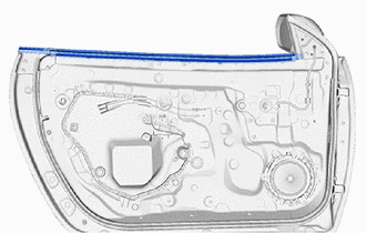
8. INSTALL FRONT DOOR GLASS OUTER WEATHERSTRIP ASSEMBLY
Click here
.gif)
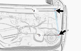
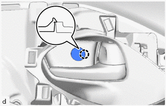
9. INSTALL FRONT DOOR LOCK OPEN ROD
(a) Engage the snap to install the front door lock open rod to the front door outside frame sub-assembly as shown in the illustration.
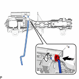
| *a | Snap |
.png) | Install in this Direction (1) |
.png) | Install in this Direction (2) |
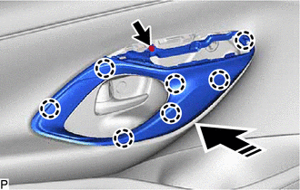
10. INSTALL FRONT DOOR OUTSIDE HANDLE FRAME SUB-ASSEMBLY
(a) Apply MP grease to the sliding parts on the front door outside handle frame sub-assembly.
(b) Engage the guides to install the front door outside handle frame sub-assembly as shown in the illustration.
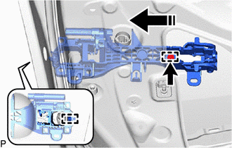
|
| Install in this Direction |
(c) Using a T30 "TORX" socket wrench, tighten the screw.
Torque:
4.0 N·m {41 kgf·cm, 35 in·lbf}
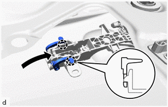
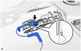
(d) w/ Entry and Start System:
| (1) Engage the clamp to install the wire harness. |
|
.png)
11. INSTALL FRONT DOOR WITH MOTOR LOCK ASSEMBLY
Click here
12. INSTALL FRONT DOOR OUTSIDE HANDLE REAR PAD
| (a) Engage the guides to install the front door outside handle rear pad. |
|
.png)
13. INSTALL FRONT DOOR OUTSIDE HANDLE FRONT PAD
| (a) Engage the guide and claws to install the front door outside handle front pad. |
|
.png)
14. INSTALL FRONT DOOR LOCK CYLINDER ASSEMBLY (for Driver Side)
| (a) Install the front door lock cylinder assembly. HINT: Check that the front door lock cylinder assembly is inserted into the front door lock with motor assembly. |
|
.png)
(b) Using a T30 "TORX" socket wrench, tighten the screw.
Torque:
4.0 N·m {41 kgf·cm, 35 in·lbf}
| (c) Install the hole plug. |
|
.png)
15. INSTALL FRONT DOOR OUTSIDE HANDLE COVER (for Front Passenger Side)
| (a) Engage the claws and guides to install the front door outside handle cover. |
|
.png)
(b) Using a T30 "TORX" socket wrench, tighten the screw.
Torque:
4.0 N·m {41 kgf·cm, 35 in·lbf}
| (c) Install the hole plug. |
|
.png)
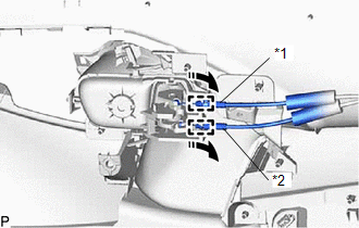
16. INSTALL FRONT DOOR OUTSIDE HANDLE ASSEMBLY
(a) Install the front door outside handle assembly as shown in the illustration.
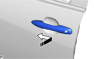
|
| Install in this Direction |
| (b) Move the lever and engage the claws as shown in the illustration. |
|
(c) w/ Entry andStart System:
| (1) Connect the connector. |
|
(2) Engage the claws.
17. INSTALL FRONT DOOR FRONT LOWER FRAME SUB-ASSEMBLY
| (a) Install the front door front lower frame sub-assembly with the bolt A and bolt B. Torque: Bolt : 8.5 N·m {87 kgf·cm, 75 in·lbf} Nut : 8.5 N·m {87 kgf·cm, 75 in·lbf} |
|
18. INSTALL FRONT DOOR GLASS RUN
| (a) Install the front door glass run. |
|
.png)
19. INSTALL DOOR GLASS FEMALE STABILIZER
| (a) Engage the guide to install the door glass female stabilizer. |
|
.png)
(b) Install the bolt.
Torque:
5.5 N·m {56 kgf·cm, 49 in·lbf}
20. INSTALL FRONT DOOR UPPER WINDOW STOP
| (a) Engage the guides to remove the 2 front door upper window stops. |
|
.png)
(b) Install the 2 bolts.
Torque:
5.5 N·m {56 kgf·cm, 49 in·lbf}
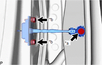
21. INSTALL FRONT DOOR WINDOW REGULATOR ASSEMBLY
| (a) Using a 4.0 mm hexagon wrench, adjust the 2 stud bolts at the bottom of the front door window regulator assembly as shown in the illustration. Standard Clearance:
|
|
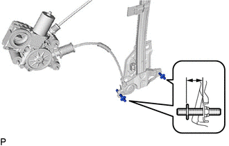
(b) Apply MP grease to the sliding and rotating areas of the front door window regulator sub-assembly LH.
(c) Temporarily install the front door window regulator assembly with the 7 nuts.
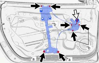
| *a | Nut (A) |
| *b | Nut (B) |
.png) | Nut |
.png) | Connector |
(d) Connect the connector.
(e) Tighten the 2 nuts (A) and 3 nuts (B).
Torque:
Nut (A) :
5.5 N·m {56 kgf·cm, 49 in·lbf}
Nut (B) :
13 N·m {133 kgf·cm, 10 ft·lbf}
22. INSTALL FRONT DOOR GLASS SUB-ASSEMBLY
(a) for Driver Side:
(1) Connect the multiplex network master switch assembly.
(2) Connect the cable to the negative (-) auxiliary battery terminal.
(3) Move the front door glass sub-assembly so that the door glass bolt holes can be seen.
(4) Disconnect the cable from the negative (-) auxiliary battery terminal.
(5) Disconnect the multiplex network master switch assembly.
(b) for Front Passenger Side:
(1) Connect the power window regulator switch assembly.
(2) Connect the cable to the negative (-) auxiliary battery terminal.
(3) Move the front door glass sub-assembly so that the door glass bolt holes can be seen.
(4) Disconnect the cable from the negative (-) auxiliary battery terminal.
(5) Disconnect the power window regulator switch assembly.
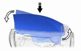
|
| Install in this Direction (1) |
|
| Install in this Direction (2) |
(c) Insert the front door glass sub-assembly into the front door panel along the front door glass run as shown in the illustration.
NOTICE:
Be careful not to damage the front door glass sub-assembly.
(d) Install the front door glass sub-assembly with the 3 nuts.
Torque:
8.0 N·m {82 kgf·cm, 71 in·lbf}
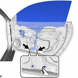
23. INSTALL WINDOW REGULATOR SHIM
| (a) Install the 2 window regulator shims. |
|
.png)
(b) Tighten the 2 nut.
Torque:
5.5 N·m {56 kgf·cm, 49 in·lbf}
24. INSPECT FRONT DOOR GLASS SUB-ASSEMBLY
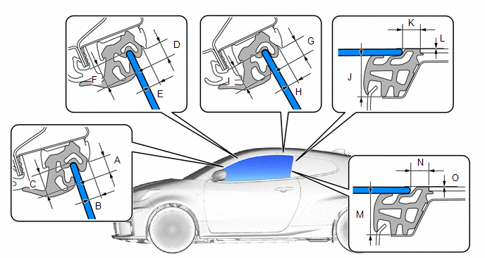
Standard Clearance:
| A | 9.2 to 13.2 mm (0.362 to 0.520 in.) | B | 6.4 to 10.4 mm (0.252 to 0.409 in.) |
| C | 15.0 mm (0.591 in.) | D | 8.4 to 12.4 mm (0.331 to 0.488 in.) |
| E | 6.4 to 10.4 mm (0.252 to 0.409 in.) | F | 15.0 mm (0.591 in.) |
| G | 8.4 to 12.4 mm (0.331 to 0.488 in.) | H | 6.4 to 10.4 mm (0.252 to 0.409 in.) |
| I | 15.0 mm (0.5906 in.) | J | 30.4 mm (1.197 in.) |
| K | 10.0 to 14.0 mm (0.394 to 0.551 in.) | L | -2.0 mm to 2.0 mm (-0.079 in to 0.079 in.) |
| M | 30.4 mm (1.197 in.) | N | 10.0 to 14.0 mm (0.394 to 0.551 in.) |
| O | -2.0 mm to 2.0 mm (-0.079 in to 0.079 in.) | - | - |
25. ADJUST FRONT DOOR GLASS SUB-ASSEMBLY
(a) Adjust the fit of the top part of the front door glass sub-assembly inward and outward.
| (1) Loosen the 2 nuts at the bottom of the front door window regulator assembly. |
|
(2) Using a 4.0 mm hexagon wrench, turn the 2 stud bolts to adjust the fit of the top part of the front door glass sub-assembly inward and outward.
HINT:
When the stud bolt are turned counterclockwise, the top part of the front door glass sub-assembly moves toward the inside of the vehicle. When the stud bolt are turned clockwise, the top part of the front door glass sub-assembly moves toward the outside of the vehicle.
(3) Tighten the 2 nuts after adjustment.
Torque:
13 N·m {133 kgf·cm, 10 ft·lbf}
(b) Adjust the fit of the bottom part of the front door glass sub-assembly inward and outward.
| (1) Loosen the 2 nuts at the top of the front door window regulator assembly. |
|
(2) Change the number of installed window regulator shims to adjust the fit of the bottom part of the front door glass sub-assembly inward and outward.
HINT:
- When more shims are used, the bottom part of the front door glass sub-assembly moves toward the outside of the vehicle. When less shims are used, the bottom part of the front door glass sub-assembly moves toward the inside of the vehicle.
- The thickness of one window regulator shim is 1.0 mm (0.039 in.).
(3) Tighten the 2 nuts after adjustment.
Torque:
5.5 N·m {56 kgf·cm, 49 in·lbf}
(c) Connect the cable to the negative (-) battery terminal.
(d) for Driver Side:
Connect the multiplex network master switch assembly.
(e) for Front Passenger Side:
Connect the power window regulator switch assembly.
(f) Adjust the front door glass sub-assembly fully closed position horizontally and vertically.
|
| Bolt |
|
| Nut |
(1) Loosen the 2 front door upper window stop bolts and temporarily move the front door upper window stops to the top of their adjustment range and then temporarily install the bolts.
(2) Loosen the 3 front door glass sub-assembly nuts.
(3) Stop the front door glass sub-assembly approximately 3 mm (0.118 in.) below the fully closed position.
(4) While holding the front door glass sub-assembly, move it vertically and horizontally to adjust its position.
(5) Tighten the 3 nuts after adjustment.
Torque:
8.0 N·m {82 kgf·cm, 71 in·lbf}
(6) Move the front door glass sub-assembly to the fully closed position.
(7) Loosen the 2 front door upper window stop bolts.
(8) While lightly pushing each front door upper window stop against the stopper on the front door glass sub-assembly, tighten each bolt.
Torque:
11.5 N·m {117 kgf·cm, 8 ft·lbf}
(g) Disconnect the cable from the negative (-) battery terminal.
CAUTION:
Wait at least 90 seconds after disconnecting the cable from the negative (-) battery terminal to disable the SRS system.
NOTICE:
When disconnecting the cable, some systems need to be initialized after the cable is reconnected.
(h) for Driver Side:
Disconnect the multiplex network master switch assembly.
(i) for Front Passenger Side:
Disconnect the power window regulator switch assembly.
26. INSTALL HOLE SEAL
| (a) Install the 2 hole seals. |
|
.png)
27. INSTALL HOLE SEAL
| (a) Install the 2 hole seals. |
|
.png)
28. INSTALL HOLE PLUG
| (a) Install the 4 hole plugs. |
|
.png)
29. INSTALL SIDE AIRBAG PRESSURE SENSOR
Click here
30. INSTALL FRONT DOOR SERVICE HOLE COVER
| (a) Pass the front door lock open lever remote control cable, front door lock/unlock knob inside locking cable and wire harness through front door service hole cover. |
|
.png)
(b) Engage the clips to install the front door service hole cover.
| (c) Engage the clamp and guides. |
|
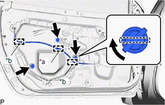
(d) Insert the 3 front door service hole cover clips and turn them 45° as shown in the illustration.
31. INSTALL OUTER REAR VIEW MIRROR ASSEMBLY
Click here
32. INSTALL NO. 1 FRONT SPEAKER BRACKET
| (a) Install the No. 1 front speaker bracket with the 3 screws. |
|
.png)
(b) Engage the guide.
33. INSTALL NO. 1 FRONT SPEAKER ASSEMBLY
Click here
34. INSTALL FRONT DOOR GLASS INNER WEATHERSTRIP
| (a) Install the front door glass inner weatherstrip. |
|
35. INSTALL FRONT DOOR INSIDE HANDLE BEZEL PLUG
| (a) Engage the claw to install the front door inside handle bezel plug. |
|
.png)
36. INSTALL FRONT DOOR INSIDE HANDLE SUB-ASSEMBLY
| (a) Engage the guides to install the front door inside handle sub-assembly. |
|
.png)
37. INSTALL NO. 1 INTERIOR ILLUMINATION LIGHT ASSEMBLY (w/ Interior Illumination)
| (a) Engage the claws to install the No. 1 interior illumination light assembly. |
|
.png)
38. INSTALL FRONT DOOR TRIM BOARD SUB-ASSEMBLY
| (a) Engage the guides to connect the front door lock remote control cable assembly and front door inside locking cable assembly. |
|
(b) Engage the claws and clips to install the front door trim board sub-assembly as shown in the illustration.
|
| Install in this Direction |
(c) Install the 3 screws.
| (d) Engage the claw to close the front door inside handle bezel plug. |
|
39. INSTALL FRONT DOOR TRIM GARNISH
(a) Engage the claws to install the front door trim garnish as shown in the illustration.
|
| Install in this Direction |
(b) Install the screw.
40. INSTALL MULTIPLEX NETWORK MASTER SWITCH ASSEMBLY WITH FRONT ARMREST BASE UPPER PANEL (for Driver Side)
(a) Connect the 2 connectors.
| (b) Engage the claws and guides to install the multiplex network master switch assembly with front door upper armrest base panel. |
|
.png)
41. INSTALL POWER WINDOW REGULATOR SWITCH ASSEMBLY WITH FRONT ARMREST BASE UPPER PANEL (for Front Passenger Side)
(a) Connect the connector.
| (b) Engage the claws and guides to install the power window regulator switch assembly with front door upper armrest base panel. |
|
.png)
42. INSTALL FRONT DOOR LOWER FRAME BRACKET GARNISH
| (a) Engage the claws and clip to install the front door lower frame bracket garnish. |
|
.png)
43. CONNECT CABLE TO NEGATIVE AUXILIARY BATTERY TERMINAL
Click here
44. INITIALIZATION AFTER RECONNECTING AUXILIARY BATTERY TERMINAL
HINT:
When disconnecting and reconnecting the auxiliary battery, there is an automatic learning function that completes learning when the respective system is used.
Click here
45. INSPECT SRS WARNING LIGHT
Click here
46. INITIALIZE POWER WINDOW CONTROL SYSTEM
Click here
47. INSPECT POWER WINDOW OPERATION
Click here
 Adjustment
ADJUSTMENT CAUTION / NOTICE / HINT
*a Centering Bolt *b Standard Bolt HINT:
Use the same procedure for the LH side and RH side.
The following procedure is for the LH side...

Other information:
Toyota Yaris XP210 (2020-2026) Reapir and Service Manual: Parts Location
PARTS LOCATION ILLUSTRATION *A w/ Ambient Illumination Light - - *1 FRONT DOOR AMBIENT ILLUMINATION LIGHT LH (FRONT DOOR TRIM BOARD SUB-ASSEMBLY LH) *2 FRONT DOOR AMBIENT ILLUMINATION LIGHT RH (FRONT DOOR TRIM BOARD SUB-ASSEMBLY RH) *3 MAP LIGHT ASSEMBLY *4 ROOM LIGHT ASSEMBLY *5 NO...
Toyota Yaris XP210 (2020-2026) Reapir and Service Manual: Brake Switch "B" Circuit Short to Battery (P070312)
DESCRIPTION The stop light switch assembly is part of a duplex system that transmits two signals: STP and ST1-. These two signals are used by the ECM to monitor whether or not the brake system is working properly. This DTC indicates that the stop light switch assembly remains on...
Categories
- Manuals Home
- Toyota Yaris Owners Manual
- Toyota Yaris Service Manual
- Power Integration No.1 System Missing Message (B235287,B235587,B235787-B235987)
- To Set Speed
- Diagnostic Trouble Code Chart
- New on site
- Most important about car
Break-In Period
No special break-in is necessary, but a few precautions in the first 600 miles (1,000 km) may add to the performance, economy, and life of the vehicle.
Do not race the engine. Do not maintain one constant speed, either slow or fast, for a long period of time. Do not drive constantly at full-throttle or high engine rpm for extended periods of time. Avoid unnecessary hard stops. Avoid full-throttle starts.