Toyota Yaris: Main Body Ecu / Components
COMPONENTS
ILLUSTRATION
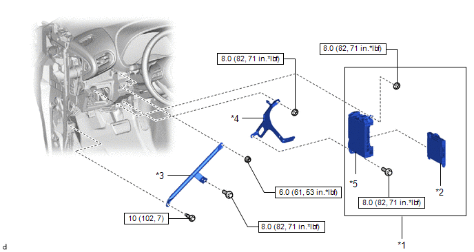
| *1 | POWER DISTRIBUTION BOX ASSEMBLY WITH MULTIPLEX NETWORK BODY ECU | *2 | MAIN BODY ECU (MULTIPLEX NETWORK BODY ECU) |
| *3 | NO. 3 INSTRUMENT PANEL TO COWL BRACE SUB-ASSEMBLY | *4 | WIRING HARNESS CLAMP BRACKET |
| *5 | POWER DISTRIBUTION BOX ASSEMBLY | - | - |
 | N*m (kgf*cm, ft.*lbf): Specified torque | - | - |

 Removal
REMOVAL CAUTION / NOTICE / HINT The necessary procedures (adjustment, calibration, initialization, or registration) that must be performed after parts are removed and installed, or replaced during the main body ECU (multiplex network body ECU) removal/installation are shown below...
Other information:
Toyota Yaris XP210 (2020-2026) Reapir and Service Manual: Road Test
ROAD TEST ROAD TEST (a) Check for DTCs. Click here Powertrain > Engine > Trouble Codes HINT: When DTCs are output, perform troubleshooting for each DTC. Click here (b) Turn the iMT switch on and off and check that the iMT indicator light illuminates and turns off...
Toyota Yaris XP210 (2020-2026) Reapir and Service Manual: Software Incompatibility with Body Control Module Not Programmed (U032251)
DESCRIPTION If the millimeter wave radar sensor assembly cannot confirm the vehicle information (steering wheel position) sent from the main body ECU (multiplex network body ECU), the millimeter wave radar sensor assembly stores DTC U032251. DTC No...
Categories
- Manuals Home
- Toyota Yaris Owners Manual
- Toyota Yaris Service Manual
- Adjustment
- Fuse Panel Description
- To Set Speed
- New on site
- Most important about car
Fuel Gauge
The fuel gauge shows approximately how much fuel is remaining in the tank when the ignition is switched ON. We recommend keeping the tank over 1/4 full.

Copyright © 2026 www.toyaris4.com