Toyota Yaris: Stop And Start System / Neutral Position Switch Circuit
DESCRIPTION
The engine stop and start ECU uses the park/neutral position switch assembly installed to the continuously variable transaxle assembly to detect when the shift lever is in P or N.
WIRING DIAGRAM
Click here

CAUTION / NOTICE / HINT
NOTICE:
-
Before replacing the engine stop and start ECU, read the number of starter operations and write it into a new engine stop and start ECU.
Click here

-
After replacing the engine stop and start ECU, perform learning of the external backup boost converter (eco run vehicle converter assembly).
Click here

-
After replacing the engine stop and start ECU or air conditioning amplifier assembly, reset and perform learning of the air conditioning information in the engine stop and start ECU.
Click here

- Inspect the fuses for circuits related to this system before performing the following procedure.
HINT:
For wire harness and connector inspection procedures and precautions, refer to "
 "
"
PROCEDURE
| 1. | READ VALUE USING GTS (NEUTRAL SWITCH) |
| Tester Display |
|---|
| Neutral Switch |
(a) Read the value when the shift lever is in neutral and any other position.
OK:
| Tester Display | Condition | Normal Condition |
|---|---|---|
| Neutral Switch | Shift lever is in neutral | ON |
| Shift lever is in any position other than neutral | OFF |
| OK |
 | GO TO PROCEED TO NEXT SUSPECTED AREA SHOWN IN PROBLEM SYMPTOMS TABLE |
|

| 2. | CHECK HARNESS AND CONNECTOR (ENGINE STOP AND START ECU - NEUTRAL POSITION SWITCH) |
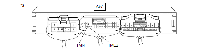
(a) Disconnect the A67 engine stop and start ECU connector.
(b) Disconnect the D44 neutral position switch connector.
(c) Measure the resistance according to the value(s) in the table below.
Standard Resistance:
| Tester Connection | Condition | Specified Condition |
|---|---|---|
| A67-26 (TMVC) - D44-1 (W1) | Always | Below 1 Ω |
| A67-25 (TME2) - D44-3 (F+) | Always | Below 1 Ω |
| A67-8 (TMN) - D44-2 (TMN) | Always | Below 1 Ω |
| A67-26 (TMVC) - Body ground and other terminals | Always | 10 kΩ or higher |
| D44-1 (W1) - Body ground and other terminals | Always | 10 kΩ or higher |
| A67-25 (TME2) - Body ground and other terminals | Always | 10 kΩ or higher |
| D44-3 (F+) - Body ground and other terminals | Always | 10 kΩ or higher |
| A67-8 (TMN) - Body ground and other terminals | Always | 10 kΩ or higher |
| D44-2 (TMN) - Body ground and other terminals | Always | 10 kΩ or higher |
| NG |
 | REPAIR OR REPLACE HARNESS OR CONNECTOR |
|

| 3. | CHECK ENGINE STOP AND START ECU (TMN TERMINAL VOLTAGE) |
| *a | Component with harness connected (Engine Stop and Start ECU) | - | - |
(a) Measure the voltage according to the value(s) in the table below.
Standard Voltage:
| Tester Connection | Condition | Specified Condition |
|---|---|---|
| A67-8 (TMN) - A67-25 (TME2) | Ignition switch ON, shift lever in neutral | 2.7 to 4.3 V |
| Ignition switch ON, shift lever in any position other than neutral | 0.7 to 1.9 V |
| OK |
 | GO TO PROCEED TO NEXT SUSPECTED AREA SHOWN IN PROBLEM SYMPTOMS TABLE |
| NG |
 | REPLACE NEUTRAL POSITION SENSOR (NEUTRAL POSITION SWITCH) |
 Backup Boost Converter Circuit
DESCRIPTION A backup boost converter is built into the engine stop and start ECU. The backup boost converter helps maintain the power source voltage when the engine is restarted by stop and start control...
 Stop and Start Cancel Switch Circuit
DESCRIPTION Stop and start control can be disabled by pressing the stop and start system cancel switch (combination switch assembly). The stop and start system cancel switch (combination switch assembly) is a momentary-type switch that switches between on and off when the switch is pressed...
Other information:
Toyota Yaris XP210 (2020-2026) Owner's Manual: Manual Transaxle Shift Pattern
The shift pattern of the transaxle is conventional, as shown. Depress the clutch pedal all the way down while shifting; then release it slowly. Your vehicle is equipped with a device to prevent shifting to R (reverse) by mistake. Push the shift lever downward and shift to R...
Toyota Yaris XP210 (2020-2026) Reapir and Service Manual: Lost Communication with Image Processing Module "A" Missing Message (U023A87)
DESCRIPTION The millimeter wave radar sensor assembly is connected to the forward recognition camera via the CAN communication line. If the millimeter wave radar sensor assembly receives signals indicating that its communication with the forward recognition camera is abnormal, the millimeter wave radar sensor assembly stores DTC U023A87...
Categories
- Manuals Home
- Toyota Yaris Owners Manual
- Toyota Yaris Service Manual
- Diagnostic Trouble Code Chart
- Engine Start Function When Key Battery is Dead
- Removal
- New on site
- Most important about car
Front Seat Belt Pretensioners
The front seat belt pretensioners are designed to deploy in moderate or severe frontal, near frontal collisions.
In addition, the pretensioners operate when a side collision or a rollover accident is detected. The pretensioners operate differently depending on what types of air bags are equipped. For more details about the seat belt pretensioner operation, refer to the SRS Air Bag Deployment Criteria.