Toyota Yaris: Main Body Ecu / Removal
REMOVAL
CAUTION / NOTICE / HINT
The necessary procedures (adjustment, calibration, initialization, or registration) that must be performed after parts are removed and installed, or replaced during the main body ECU (multiplex network body ECU) removal/installation are shown below.
Necessary Procedure After Parts Removed/Installed/Replaced| Replacement Part or Procedure | Necessary Procedures | Effects/Inoperative when not performed | Link |
|---|---|---|---|
| Main body ECU (multiplex network body ECU) | Code registration |
|
|
| ECU configuration | - |
|


HINT:
When the cable is disconnected / reconnected to the auxiliary battery terminal, systems temporarily stop operating. However, each system has a function that completes learning the first time the system is used.
-
Learning completes when vehicle is driven
Effect/Inoperative Function When Necessary Procedures are not Performed
Necessary Procedures
Link
Lane tracing assist system
Drive the vehicle straight ahead at 35 km/h (22 mph) or more for 5 second or more.

Pre-collision system
Stop and start system
Drive the vehicle until stop and start control is permitted (approximately 5 to 60 minutes)

-
Learning completes when vehicle is operated normally
Effect/Inoperative Function When Necessary Procedures are not Performed
Necessary Procedures
Link
Power door lock control system
- Back door opener
Perform door unlock operation with door control switch or electrical key transmitter sub-assembly switch.

Air conditioning system
After the ignition switch is turned to ON, the servo motor standard position is recognized.
-
PROCEDURE
1. PRECAUTION
NOTICE:
After turning the ignition switch off, waiting time may be required before disconnecting the cable from the negative (-) auxiliary battery terminal.
Click here

2. DISCONNECT CABLE FROM NEGATIVE AUXILIARY BATTERY TERMINAL
Click here

3. REMOVE LOWER INSTRUMENT PANEL FINISH PANEL ASSEMBLY
Click here

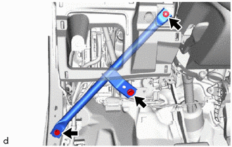
4. REMOVE NO. 3 INSTRUMENT PANEL TO COWL BRACE SUB-ASSEMBLY
| (a) Remove the 2 bolts, nut and No. 3 instrument panel to cowl brace sub-assembly. |
|
5. REMOVE POWER DISTRIBUTION BOX ASSEMBLY WITH MULTIPLEX NETWORK BODY ECU
| (a) Disconnect the 5 connectors. |
|
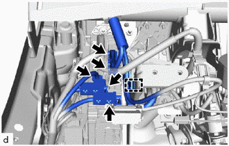
(b) Disengage the clamp.
| (c) Disengage the claws and pull up the lock levers to disconnect the 2 connectors as shown in the illustration. |
|
(d) Disengage the clamp.
| (e) Disconnect the 5 connectors. |
|
| (f) Remove the 2 nuts. |
|
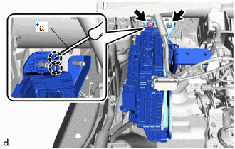
(g) Using a screwdriver with its tip wrapped in protective tape, disengage the claws as shown in the illustration.
(h) Pull out the power distribution box assembly with multiplex network body ECU.
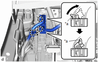
| (i) Disengage the claws. |
|
| (j) Disengage the claws and pull up the lock levers to disconnect the 2 connectors as shown in the illustration. |
|
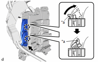
(k) Disconnect the connector.
(l) Remove the power distribution box assembly with multiplex network body ECU.
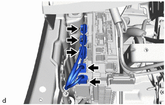
6. REMOVE WIRING HARNESS CLAMP BRACKET
| (a) Remove the bolt. |
|
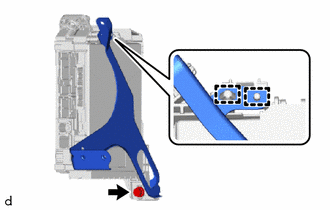
(b) Disengage the guides to remove the wiring harness clamp bracket.
7. REMOVE MAIN BODY ECU (MULTIPLEX NETWORK BODY ECU)
(a) Push the claw of the power distribution box assembly as shown in the illustration to release the lock.
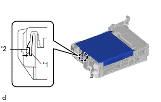
| *1 | Power Distribution Box Assembly |
| *2 | Main Body ECU (Multiplex Network Body ECU) |
 | Push |
(b) With the power distribution box assembly lock released, insert a screwdriver with its tip wrapped in protective tape horizontally between the main body ECU (multiplex network body ECU) and the power distribution box assembly.
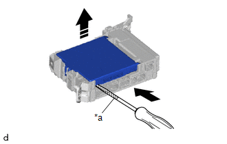
| *a | Protective Tape |
 | Insert |
 | Raise in this Direction |
NOTICE:
- Use a screwdriver with a diameter between 5.0 mm (0.197 in.) and 6.3 mm (0.248 in.) and a length of approximately 90 mm (3.54 in.).
- Do not insert the screwdriver under the connector socket of the main body ECU (multiplex network body ECU).
(c) Using the screwdriver, carefully raise the main body ECU (multiplex network body ECU) to the position where the connector becomes disconnected.
NOTICE:
Do not twist the screwdriver to raise the main body ECU (multiplex network body ECU).
(d) Remove the main body ECU (multiplex network body ECU) as shown in the illustration.
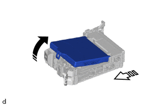
 | Remove in this Direction (1) |
 | Remove in this Direction (2) |
NOTICE:
Do not touch the main body ECU (multiplex network body ECU) connector.
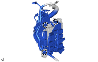
 Components
COMPONENTS ILLUSTRATION
*1 POWER DISTRIBUTION BOX ASSEMBLY WITH MULTIPLEX NETWORK BODY ECU *2 MAIN BODY ECU (MULTIPLEX NETWORK BODY ECU) *3 NO...
 Installation
INSTALLATION PROCEDURE 1. INSTALL MAIN BODY ECU (MULTIPLEX NETWORK BODY ECU) NOTICE:
Make sure that the connecting surfaces are free of foreign matter...
Other information:
Toyota Yaris XP210 (2020-2026) Reapir and Service Manual: Installation
INSTALLATION CAUTION / NOTICE / HINT HINT: Use the same procedure for the RH side and LH side. The following procedure is for the LH side. PROCEDURE 1. INSTALL FRONT AIRBAG SENSOR (a) Check that the ignition switch is off. (b) Check that the cable is disconnected from the negative (-) auxiliary battery terminal...
Toyota Yaris XP210 (2020-2026) Reapir and Service Manual: Camshaft Position Sensor "B" Bank 1 Circuit Short to Ground (P036511,P036515)
DESCRIPTION The camshaft position sensor (for exhaust camshaft) (EV1 signal) consists of a magnet and MRE (Magneto Resistance Element). The exhaust camshaft has a timing rotor for the camshaft position sensor. When the exhaust camshaft rotates, changes occur in the air gaps between the timing rotor and MRE, which affects the magnetic field...
Categories
- Manuals Home
- Toyota Yaris Owners Manual
- Toyota Yaris Service Manual
- Auto Lock/Unlock Function
- Battery Monitor Module General Electrical Failure (P058A01)
- Power Integration No.1 System Missing Message (B235287,B235587,B235787-B235987)
- New on site
- Most important about car
Break-In Period
No special break-in is necessary, but a few precautions in the first 600 miles (1,000 km) may add to the performance, economy, and life of the vehicle.
Do not race the engine. Do not maintain one constant speed, either slow or fast, for a long period of time. Do not drive constantly at full-throttle or high engine rpm for extended periods of time. Avoid unnecessary hard stops. Avoid full-throttle starts.