Toyota Yaris: Main Body Ecu / Installation
INSTALLATION
PROCEDURE
1. INSTALL MAIN BODY ECU (MULTIPLEX NETWORK BODY ECU)
NOTICE:
- Make sure that the connecting surfaces are free of foreign matter.
- Do not touch the main body ECU (multiplex network body ECU) connector.
(a) Set the main body ECU (multiplex network body ECU) to the position where the guide of the main body ECU (multiplex network body ECU) contacts the housing sidewall of the power distribution box assembly as shown in the illustration.
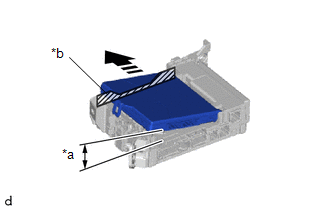
| *a | 20° or more |
| *b | Housing Sidewall |
 | Set in this Direction |
HINT:
Make sure to keep the angle at 20° or more as shown in the illustration.
(b) Slide the main body ECU (multiplex network body ECU) along the housing sidewall as shown in the illustration and engage the guides.
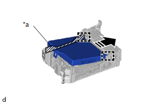
| *a | Housing Sidewall |
 | Slide in this Direction |
(c) While keeping the main body ECU (multiplex network body ECU) in contact with side A of the power distribution box assembly (axis of rotation), lower it as shown in the illustration.
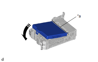
| *a | Side A |
 | Lower in this Direction |
NOTICE:
Do not strike or apply excessive force to the side surface of the main body ECU (multiplex network body ECU).
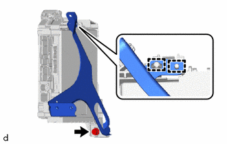
(d) Press the push area until the claw engages to install the main body ECU (multiplex network body ECU).
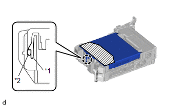
| *1 | Power Distribution Box Assembly |
| *2 | Main Body ECU (Multiplex Network Body ECU) |
 | Push Area |
NOTICE:
- Make sure to press only the push area.
- Confirm the engagement of the main body ECU (multiplex network body ECU) and power distribution box assembly by listening for the click sound of the lock engaging.
HINT:
If a click sound cannot be heard, visually check the engagement of the lock. The engagement can also be confirmed if the main body ECU (multiplex network body ECU) and power distribution box assembly are flush.
2. INSTALL WIRING HARNESS CLAMP BRACKET
| (a) Engage the guides to install the wiring harness clamp bracket to the power distribution box assembly with multiplex network body ECU. |
|
(b) Temporarily install the bolt.
3. INSTALL POWER DISTRIBUTION BOX ASSEMBLY WITH MULTIPLEX NETWORK BODY ECU
| (a) Connect the connector. |
|
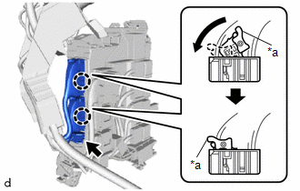
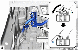
(b) Connect the 2 connectors and pull down the lock levers to engage the claws and lock the 2 connectors as shown in the illustration.
| (c) Engage the claws. |
|
| (d) Engage the claws. |
|
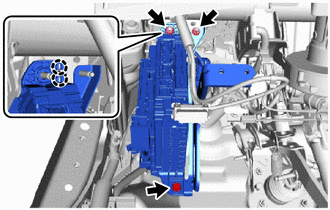
(e) Install the power distribution box assembly with multiplex network body ECU with the bolt and 2 nuts.
Torque:
Nut :
8.0 N·m {82 kgf·cm, 71 in·lbf}
Bolt :
8.0 N·m {82 kgf·cm, 71 in·lbf}
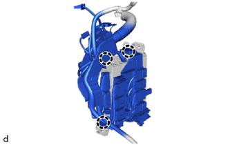
(f) Connect the 5 connectors.
| (g) Connect the 2 connectors and pull down the lock levers to engage the claws and lock the 2 connectors as shown in the illustration. |
|
(h) Engage the clamp.
| (i) Engage the clamp. |
|
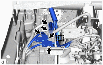
(j) Connect the 5 connectors.
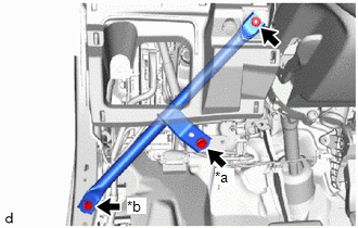
4. INSTALL NO. 3 INSTRUMENT PANEL TO COWL BRACE SUB-ASSEMBLY
| (a) Install the No. 3 instrument panel to cowl brace sub-assembly with the 2 bolts and nut. Torque: Nut : 6.0 N·m {61 kgf·cm, 53 in·lbf} Bolt (A) : 8.0 N·m {82 kgf·cm, 71 in·lbf} Bolt (B) : 10 N·m {102 kgf·cm, 7 ft·lbf} |
|
5. INSTALL LOWER INSTRUMENT PANEL FINISH PANEL ASSEMBLY
Click here

6. CONNECT CABLE TO NEGATIVE AUXILIARY BATTERY TERMINAL
Click here

7. ECU CONFIGURATION
Click here

8. INITIALIZATION AFTER RECONNECTING AUXILIARY BATTERY TERMINAL
HINT:
When disconnecting and reconnecting the auxiliary battery, there is an automatic learning function that completes learning when the respective system is used.
Click here

 Removal
REMOVAL CAUTION / NOTICE / HINT The necessary procedures (adjustment, calibration, initialization, or registration) that must be performed after parts are removed and installed, or replaced during the main body ECU (multiplex network body ECU) removal/installation are shown below...

Other information:
Toyota Yaris XP210 (2020-2026) Reapir and Service Manual: Dtc Check / Clear
DTC CHECK / CLEAR CHECK DTC (a) Check semiconductor power integration ECU (1) Check for DTCs. Body Electrical > Power Integration No.1 > Trouble Codes (b) Check power distribution box assembly (1) Check for DTCs. Body Electrical > Power Distribution Box > Trouble Codes CLEAR DTC (a) Check semiconductor power integration ECU (1) Clear the DTCs...
Toyota Yaris XP210 (2020-2026) Reapir and Service Manual: Components
COMPONENTS ILLUSTRATION *A for Driver Side *B for Front Passenger Side *1 FRONT SEAT VERTICAL ADJUSTER HANDLE *2 NO.1 RECLINING HINGE COVER *3 RECLINING ADJUSTER RELEASE HANDLE *4 SEAT ADJUSTER COVER CAP *5 FRONT SEAT CUSHION SHIELD *6 FRONT SEAT INNER CUSHION SHIELD ILLUSTRATION *1 SEPARATE TYPE FRONT SEATBACK ASSEMBLY - - Tightening torque for "Major areas involving basic vehicle performance such as moving/turning/stopping" : N*m (kgf*cm, ft...
Categories
- Manuals Home
- Toyota Yaris Owners Manual
- Toyota Yaris Service Manual
- Key Battery Replacement
- Diagnostic Trouble Code Chart
- Fuel Gauge
- New on site
- Most important about car
Supplemental Restraint System (SRS) Precautions
The front and side supplemental restraint systems (SRS) include different types of air bags. Please verify the different types of air bags which are equipped on your vehicle by locating the “SRS AIRBAG” location indicators. These indicators are visible in the area where the air bags are installed.
The air bags are installed in the following locations:
The steering wheel hub (driver air bag) The front passenger dashboard (front passenger air bag) The outboard sides of the front seatbacks (side air bags) The front and rear window pillars, and the roof edge along both sides (curtain air bags)