Toyota Yaris: Hood / Adjustment
ADJUSTMENT
CAUTION / NOTICE / HINT
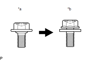
| *a | Centering Bolt |
| *b | Standard Bolt |
HINT:
- Centering bolts are used to install the hood hinges and hood lock. The hood and hood lock cannot be adjusted with the centering bolts installed. Substitute the centering bolts with standard bolts with washers when making adjustments.
-
The specified torque for standard bolts is shown in the standard bolt chart.
Click here
.gif)
PROCEDURE
1. INSPECT HOOD SUB-ASSEMBLY
Click here
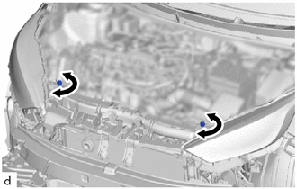
2. REMOVE FRONT BUMPER ASSEMBLY
Click here
3. REMOVE RADIATOR UPPER AIR GUIDE PLATE
Click here
4. REMOVE HOOD SUB-ASSEMBLY
(a) Horizontally and vertically adjust the hood.
| (1) Loosen the 4 hinge bolts of the hood. |
|
(2) Adjust the clearance between the hood and front fenders by moving the hood.
(3) Tighten the 4 hinge bolts after adjustment.
Torque:
13 N·m {133 kgf·cm, 10 ft·lbf}
(b) Adjust the height of the front end of the hood using the hood bumper cushions.
| (1) Adjust the 2 hood bumper cushions so that the heights of the hood and fenders are aligned. HINT: Raise or lower the front end of the hood by turning the 2 hood bumper cushions. |
|
(c) Adjust the hood lock.
| (1) Loosen the 3 bolts. |
|
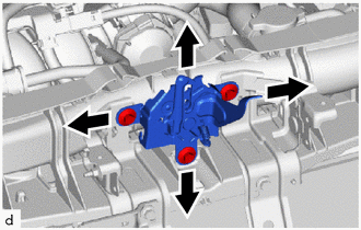
(2) Adjust the hood lock assembly and tighten the 3 bolts.
Torque:
11.5 N·m {117 kgf·cm, 8 ft·lbf}
NOTICE:
At the time of adjustment, use the supply hood lock assembly.
(3) Check that the striker can engage the hood lock assembly smoothly.
5. INSTALL RADIATOR UPPER AIR GUIDE PLATE
Click here
6. INSTALL FRONT BUMPER ASSEMBLY
Click here
 Disassembly
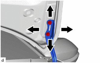
DISASSEMBLY PROCEDURE 1. REMOVE HOOD INSULATOR (a) Remove the 4 clips.
(b) Disengage the guides to remove the hood insulator. 2. REMOVE HOOD STAY HOLDER (a) Disengage the claws to remove the hood stay holder...
 Reassembly
REASSEMBLY PROCEDURE 1. INSTALL HOOD BUMPER CUSHION (a) Rotate clockwise to install the 2 hood bumper cushions.
2. INSTALL HOOD SUPPORT ASSEMBLY (a) Engage the claws to install the hood support assembly...
Other information:
Toyota Yaris XP210 (2020-2026) Reapir and Service Manual: Problem Symptoms Table
PROBLEM SYMPTOMS TABLE HINT: Use the table below to help determine the cause of problem symptoms. If multiple suspected areas are listed, the potential causes of the symptoms are listed in order of probability in the "Suspected Area" column of the table...
Toyota Yaris XP210 (2020-2026) Owner's Manual: Height Adjustment
Adjust the head restraint so that the center is even with the top of the passenger’s ears. To raise a head restraint, pull it up to the desired position. To lower the head restraint, press the stop-catch release, then push the head restraint down...
Categories
- Manuals Home
- Toyota Yaris Owners Manual
- Toyota Yaris Service Manual
- Opening and Closing the Liftgate/Trunk Lid
- Removal
- How to use USB mode
- New on site
- Most important about car
Break-In Period
No special break-in is necessary, but a few precautions in the first 600 miles (1,000 km) may add to the performance, economy, and life of the vehicle.
Do not race the engine. Do not maintain one constant speed, either slow or fast, for a long period of time. Do not drive constantly at full-throttle or high engine rpm for extended periods of time. Avoid unnecessary hard stops. Avoid full-throttle starts.