Toyota Yaris: Wireless Door Lock Control System / Wireless Door Lock Tuner Component Internal Failure (B124296)
DESCRIPTION
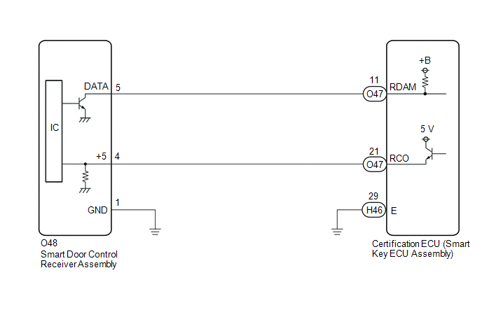
The smart door control receiver assembly is used to receive radio waves related to the entry functions of the electrical key transmitter sub-assembly. The certification ECU (smart key ECU assembly) decodes the requested electrical key transmitter sub-assembly operation by identifying a key code based on the radio waves received via the smart door control receiver assembly. The smart door control receiver assembly receives a signal from the electrical key transmitter sub-assembly and sends signals to the main body ECU (multiplex network body ECU) through the certification ECU (smart key ECU assembly). (ex. If a door lock operation is requested, the certification ECU (smart key ECU assembly) sends a door lock command to the main body ECU (multiplex network body ECU)).
| DTC No. | Detection Item | DTC Detection Condition | Trouble Area |
|---|---|---|---|
| B124296 | Wireless Door Lock Tuner Component Internal Failure |
|
|
WIRING DIAGRAM
CAUTION / NOTICE / HINT
NOTICE:
- When using the GTS with the ignition switch off, connect the GTS to the DLC3 and turn a courtesy light switch on and off at intervals of 1.5 seconds or less until communication between the GTS and the vehicle begins. Then select the vehicle type under manual mode and enter the following menus: Body Electrical / Smart Key. While using the GTS, periodically turn a courtesy light switch on and off at intervals of 1.5 seconds or less to maintain communication between the GTS and the vehicle.
-
Before replacing the certification ECU (smart key ECU assembly), refer to Registration.
Click here

- When replacing or inspecting the smart door control receiver assembly and wire harness, do not change the position or length of the wire harness. If the wire harness is too close to the smart door control receiver assembly, the performance of the entry function and wireless function may be affected.
- This DTC is not stored within 10 seconds of the ignition switch being turned from on to off.
- Make sure that there are no electrical key transmitter sub-assemblies in the vehicle.
PROCEDURE
| 1. | CHECK CERTIFICATION ECU (SMART KEY ECU ASSEMBLY) |
(a) Disconnect the O48 smart door control receiver assembly connector.
(b) Measure the voltage and resistance and check for pulses according to the value(s) in the table below.
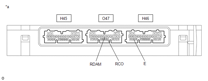
| *a | Component with harness connected (Certification ECU (Smart Key ECU Assembly)) | - | - |
Standard Resistance:
| Tester Connection | Condition | Specified Condition |
|---|---|---|
| H46-29 (E) - Body ground | Always | Below 1 Ω |
Standard Voltage:
| Tester Connection | Condition | Specified Condition |
|---|---|---|
| O47-11 (RDAM) - H46-29 (E) | Ignition switch off | 11 to 14 V |
| O47-21 (RCO) - H46-29 (E) | Always | Below 1 V → 4.5 to 5.5 V pulse generation at regular intervals |
| OK |
 | REPLACE SMART DOOR CONTROL RECEIVER ASSEMBLY |
|

| 2. | CHECK HARNESS AND CONNECTOR (SMART DOOR CONTROL RECEIVER ASSEMBLY - CERTIFICATION ECU (SMART KEY ECU ASSEMBLY)) |
(a) Disconnect the O47 certification ECU (smart key ECU assembly) connector.
(b) Measure the resistance according to the value(s) in the table below.
Standard Resistance:
| Tester Connection | Condition | Specified Condition |
|---|---|---|
| O47-11(RDAM) - O48-5 (DATA) | Always | Below 1 Ω |
| O47-21 (RCO) - O48-4 (+5) | Always | Below 1 Ω |
| O48-1 (GND) - Body ground | Always | Below 1 Ω |
| O48-5 (DATA) or O47-11 (RDAM) - Other terminals and body ground | Always | 10 kΩ or higher |
| O48-4 (+5) or O47-21 (RCO) - Other terminals and body ground | Always | 10 kΩ or higher |
| OK |
 | REPLACE CERTIFICATION ECU (SMART KEY ECU ASSEMBLY) |
| NG |
 | REPAIR OR REPLACE HARNESS OR CONNECTOR |

 No Answer-Back
DESCRIPTION In some cases, wireless door lock control functions are normal but the hazard warning light do not operate. In such cases, hazard warning light outputs from the main body ECU (multiplex network body ECU) may be malfunctioning...
Other information:
Toyota Yaris XP210 (2020-2026) Reapir and Service Manual: Brake System Control Module "A" System Voltage System Voltage Low (C137BA2)
DESCRIPTION If a malfunction is detected in the power supply circuit, the skid control ECU (brake actuator assembly) stores this DTC and the fail-safe function prohibits ABS operation. This DTC is stored when the +BS terminal voltage meets one of the DTC detection conditions due to a malfunction in the power supply or charging circuit such as the auxiliary battery or alternator circuit, etc...
Toyota Yaris XP210 (2020-2026) Reapir and Service Manual: Lost Communication with Front Panel LIN Missing Message (B14B287)
DESCRIPTION The air conditioning control assembly communicates with the air conditioning amplifier assembly via LIN communication. If a malfunction occurs in the LIN communication system, the air conditioning amplifier assembly will not operate, even if the air conditioning control assembly is operated...
Categories
- Manuals Home
- Toyota Yaris Owners Manual
- Toyota Yaris Service Manual
- Fuel Gauge
- How to connect USB port/Auxiliary jack
- Battery Monitor Module General Electrical Failure (P058A01)
- New on site
- Most important about car
Front Seat Belt Pretensioners
The front seat belt pretensioners are designed to deploy in moderate or severe frontal, near frontal collisions.
In addition, the pretensioners operate when a side collision or a rollover accident is detected. The pretensioners operate differently depending on what types of air bags are equipped. For more details about the seat belt pretensioner operation, refer to the SRS Air Bag Deployment Criteria.