Toyota Yaris: Sfi System / Throttle/Pedal Position Sensor "A" Minimum Stop Performance (P210900)
DESCRIPTION
The idle speed is controlled by the Electronic Throttle Control System (ETCS). The ETCS is comprised of a throttle actuator, which operates the throttle valve, and a throttle position sensor, which detects the opening amount of the throttle valve. The ECM controls the throttle actuator to adjust the throttle valve opening amount so that the idle speed is maintained at the target idle speed.
| DTC No. | Detection Item | DTC Detection Condition | Trouble Area | MIL | Note |
|---|---|---|---|---|---|
| P210900 | Throttle/Pedal Position Sensor "A" Minimum Stop Performance | The Throttle Air Flow F/B Value* approaches its limit even though the actual intake air amount during idling is within the normal range (up to 1.5 times the normal amount) (5 trip detection logic). *: Data List item | Throttle body with motor assembly | - | SAE: P2109 |
HINT:
- This malfunction is only detected once per trip. After it has been detected once, the system will not monitor for the malfunction for the rest of the trip.
- The system uses the throttle body with motor assembly and mass air flow meter sub-assembly to detect this malfunction.
MONITOR DESCRIPTION
If there are deposits in the throttle valve, a decrease in the ISC flow rate may cause engine stall or unstable idling. Therefore, the necessary ISC flow rate for idling is maintained using the throttle air flow feedback. The ECM stores this DTC if the Throttle Air Flow F/B Value approaches its limit. The ECM begins monitoring for the DTC detection conditions when the following preconditions are met:
- The mass air flow meter sub-assembly is normal.
- Atmospheric pressure is 85 kPa(abs) [12.3 psi(abs)] or higher.
- The vehicle has been driven at a speed of 30 km/h (19 mph) or more at least once.
- The engine coolant temperature is 45°C (113°F) or less at engine start, the engine is warmed up and conditions for Throttle Air Flow F/B Value are met, or the ignition switch has been turned on (IG) (include engine running) for 1 hour or more, the engine is warmed up and conditions for Throttle Air Flow F/B Value are met.
CAUTION / NOTICE / HINT
HINT:
- Since a pending DTC is not stored for this DTC, it takes time to confirm whether the malfunction has been successfully repaired by checking for this DTC. When confirming whether the malfunction has been successfully repaired, compare "Throttle Air Flow F/B Value" recorded in the Freeze Frame Data with "Throttle Air Flow F/B Value" in the Data List after repairs have been made to save time.
- Read Freeze Frame Data using the GTS. The ECM records vehicle and driving condition information as Freeze Frame Data the moment a DTC is stored. When troubleshooting, Freeze Frame Data can help determine if the vehicle was moving or stationary, if the engine was warmed up or not, if the air fuel ratio was lean or rich, and other data from the time the malfunction occurred.
PROCEDURE
| 1. | CHECK ANY OTHER DTCS OUTPUT (IN ADDITION TO DTC P210900) |
(a) Read the DTCs.
Powertrain > Engine > Trouble Codes| Result | Proceed to |
|---|---|
| P210900 is output | A |
| P210900 and other DTCs are output | B |
HINT:
If any DTCs other than P210900 are output, troubleshoot those DTCs first.
| B |
 | GO TO DTC CHART |
|

| 2. | READ FREEZE FRAME DATA (THROTTLE AIR FLOW F/B VALUE) |
(a) Connect the GTS to the DLC3.
(b) Turn the ignition switch to ON.
(c) Turn the GTS on.
(d) Using the GTS, check "Throttle Air Flow F/B Value" in the Freeze Frame Data.
Click here

HINT:
Be sure to confirm "Throttle Air Flow F/B Value" in the Freeze Frame Data as it is used when confirming whether the malfunction has been successfully repaired.
|

| 3. | INSPECT THROTTLE BODY WITH MOTOR ASSEMBLY |
(a) Check for foreign matter between the throttle valve and the housing.
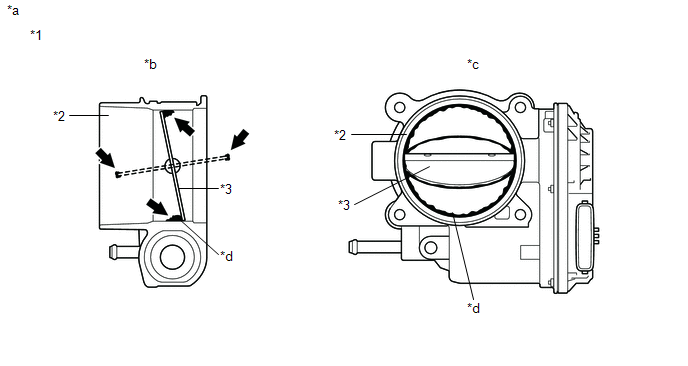
| *1 | Throttle Body with Motor Assembly | *2 | Bore |
| *3 | Throttle Valve | - | - |
| *a | Reference | *b | Throttle Body with Motor Assembly Cross-section Diagram |
| *c | When valve fully opened | *d | Deposits |
HINT:
The illustration is for reference only, actual parts may differ.
| Result | Proceed to |
|---|---|
| Foreign matter between the throttle valve and housing | A |
| No foreign matter between the throttle valve and housing | B |
HINT:
-
When cleaning or replacing one throttle body with motor assembly, clean the other throttle body with motor assembly.
Click here REMOVE FOREIGN MATTER (CLEAN THROTTLE BODY WITH MOTOR ASSEMBLY)
-
Perform "Inspection After Repair" after replacing the throttle body with motor assembly.
Click here

| B |
 | REPLACE THROTTLE BODY WITH MOTOR ASSEMBLY |
|

| 4. | REMOVE FOREIGN MATTER (CLEAN THROTTLE BODY WITH MOTOR ASSEMBLY) |
(a) Clean off any deposits inside of the throttle body with motor assembly.
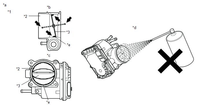
| *1 | Throttle Body with Motor Assembly | *2 | Bore |
| *3 | Throttle Valve | - | - |
| *a | Reference | *b | Throttle Body with Motor Assembly Cross-section Diagram |
| *c | When valve fully opened | *d | Do not directly apply cleaner |
| *e | Deposits | - | - |
(1) Push open the throttle valve and wipe off any deposits from the valve and bore using a cloth soaked in non-residue solvent.
NOTICE:
- Make sure that the cloth or your fingers do not get caught in the valve.
- Make sure that foreign matter does not enter the throttle valve.
- Do not directly apply non-residue solvent to the throttle body with motor assembly or wash the throttle body with motor assembly. Cleaning solvent may leak into the motor from the shaft and cause problems such as rust or valve movement problems.
- If there is coating material on the edge of the throttle valve, be careful not to remove it.
- Push the throttle valve open gently with your finger and check that the throttle valve moves smoothly.
HINT:
-
If the throttle valve does not open smoothly, replace the throttle body with motor assembly.
Click here

- The illustration is for reference only, actual parts may differ.
- When cleaning or replacing one throttle body with motor assembly, clean the other throttle body with motor assembly.
|

| 5. | READ VALUE USING GTS (THROTTLE AIR FLOW F/B VALUE) |
(a) Perform "Inspection After Repair" after cleaning the throttle body with motor assembly.
Click here

(b) Enter the following menus.
Powertrain > Engine > Data List| Tester Display |
|---|
| Throttle Air Flow F/B Value |
(c) According to the display on the GTS, read the Data List.
OK:
The value is half of "Throttle Air Flow F/B Value" recorded in the Freeze Frame Data or less.
HINT:
-
When cleaning or replacing one throttle body with motor assembly, clean the other throttle body with motor assembly.
Click here REMOVE FOREIGN MATTER (CLEAN THROTTLE BODY WITH MOTOR ASSEMBLY)
-
Perform "Inspection After Repair" after replacing the throttle body with motor assembly.
Click here

| OK |
 | END |
| NG |
 | REPLACE THROTTLE BODY WITH MOTOR ASSEMBLY |
 Throttle Actuator "A" Control Motor Circuit Current Below Threshold (P210018,P210019)
DESCRIPTION The throttle actuator is operated by the ECM and opens and closes the throttle valve using gears. The opening angle of the throttle valve is detected by the throttle position sensor, which is mounted on the throttle body with motor assembly...
 Throttle Actuator "A" Control System Actuator Stuck Open (P211172,P211173)
DESCRIPTION The throttle actuator is operated by the ECM, and opens and closes the throttle valve using gears. The opening angle of the throttle valve is detected by the throttle position sensor, which is mounted on the throttle body with motor assembly...
Other information:
Toyota Yaris XP210 (2020-2026) Reapir and Service Manual: Front Door Courtesy Switch Circuit
DESCRIPTION The main body ECU (multiplex network body ECU) detects the condition of the front door courtesy light switch assembly. WIRING DIAGRAM CAUTION / NOTICE / HINT NOTICE: Before replacing the main body ECU (multiplex network body ECU), refer to Registration...
Toyota Yaris XP210 (2020-2026) Reapir and Service Manual: A Camshaft Position Actuator Bank 1 Circuit Open (P001013)
DESCRIPTION The Variable Valve Timing (VVT) system adjusts the intake valve timing to improve driveability. The engine oil pressure turns the VVT controller to adjust the valve timing. The cam timing oil control solenoid assembly (for intake camshaft) operates according to signals received from the ECM to control the position of the camshaft timing oil control valve assembly and supply engine oil...
Categories
- Manuals Home
- Toyota Yaris Owners Manual
- Toyota Yaris Service Manual
- How to use USB mode
- Brake System Control Module "A" System Voltage System Voltage Low (C137BA2)
- Headlights
- New on site
- Most important about car
Supplemental Restraint System (SRS) Precautions
The front and side supplemental restraint systems (SRS) include different types of air bags. Please verify the different types of air bags which are equipped on your vehicle by locating the “SRS AIRBAG” location indicators. These indicators are visible in the area where the air bags are installed.
The air bags are installed in the following locations:
The steering wheel hub (driver air bag) The front passenger dashboard (front passenger air bag) The outboard sides of the front seatbacks (side air bags) The front and rear window pillars, and the roof edge along both sides (curtain air bags)