Toyota Yaris: Sfi System / A Camshaft Position Actuator Bank 1 Circuit Open (P001013)
DESCRIPTION
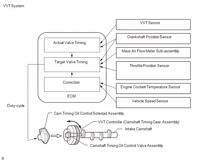
The Variable Valve Timing (VVT) system adjusts the intake valve timing to improve driveability. The engine oil pressure turns the VVT controller to adjust the valve timing.
The cam timing oil control solenoid assembly (for intake camshaft) operates according to signals received from the ECM to control the position of the camshaft timing oil control valve assembly and supply engine oil. The camshaft timing oil control valve assembly moves when the ECM applies 12 V to the cam timing oil control solenoid assembly (for intake camshaft). The ECM changes the energizing time of the cam timing oil control solenoid assembly (for intake camshaft) duty-cycle in accordance with the camshaft position, crankshaft position, throttle position, etc.
| DTC No. | Detection Item | DTC Detection Condition | Trouble Area | MIL | Note |
|---|---|---|---|---|---|
| P001013 | A Camshaft Position Actuator Bank 1 Circuit Open | Open or short in cam timing oil control solenoid assembly (for intake camshaft of) circuit (1 trip detection logic). |
| Comes on | SAE: P0010 |
MONITOR DESCRIPTION
This DTC is designed to detect an open or short in the cam timing oil control solenoid assembly (for intake camshaft) circuit. If the cam timing oil control solenoid duty-cycle is excessively high or low while the ignition switch is ON or the engine is running, the ECM will illuminate the MIL and store this DTC.
MONITOR STRATEGY
| Required Sensors/Components | Cam timing oil control solenoid assembly (for intake camshaft) |
| Frequency of Operation | Continuous |
CONFIRMATION DRIVING PATTERN
- Connect the GTS to the DLC3.
- Turn the ignition switch to ON.
- Turn the GTS on.
- Clear the DTCs (even if no DTCs are stored, perform the clear DTC procedure).
- Turn the ignition switch off and wait for at least 30 seconds.
- Start the engine [A].
- Wait 5 seconds or more [B].
- Turn the GTS on.
- Enter the following menus: Powertrain / Engine / Trouble Codes [C].
-
Read the pending DTCs.
HINT:
- If a pending DTC is output, the system is malfunctioning.
- If a pending DTC is not output, perform the following procedure.
- Enter the following menus: Powertrain / Engine / Utility / All Readiness.
- Input the DTC: P001013.
-
Check the DTC judgment result.
GTS Display
Description
NORMAL
- DTC judgment completed
- System normal
ABNORMAL
- DTC judgment completed
- System abnormal
INCOMPLETE
- DTC judgment not completed
- Perform driving pattern after confirming DTC enabling conditions
HINT:
- If the judgment result is NORMAL, the system is normal.
- If the judgment result is ABNORMAL, the system has a malfunction.
- If the judgment result is INCOMPLETE, perform steps [A] through [C] again.
WIRING DIAGRAM
CAUTION / NOTICE / HINT
HINT:
Read Freeze Frame Data using the GTS. The ECM records vehicle and driving condition information as Freeze Frame Data the moment a DTC is stored. When troubleshooting, Freeze Frame Data can help determine if the vehicle was moving or stationary, if the engine was warmed up or not, if the air fuel ratio was lean or rich, and other data from the time the malfunction occurred.
PROCEDURE
| 1. | READ OUTPUT DTC (DTC P001013) |
(a) Clear the DTC after recording the freeze frame data and DTC.
Powertrain > Engine > Clear DTCs(b) Turn the ignition switch off and wait for at least 30 seconds.
(c) Start the engine.
(d) Read the DTCs.
Powertrain > Engine > Trouble Codes| Result | Proceed to |
|---|---|
| P001013 is output | A |
| DTCs are not output | B |
| B |
 | CHECK FOR INTERMITTENT PROBLEMS |
|

| 2. | INSPECT CAM TIMING OIL CONTROL SOLENOID ASSEMBLY (FOR INTAKE CAMSHAFT) |
Click here

| NG |
 | REPLACE CAM TIMING OIL CONTROL SOLENOID ASSEMBLY (FOR INTAKE CAMSHAFT) |
|

| 3. | CHECK HARNESS AND CONNECTOR (CAM TIMING OIL CONTROL SOLENOID ASSEMBLY (FOR INTAKE CAMSHAFT) - ECM) |
(a) Disconnect the cam timing oil control solenoid assembly (for intake camshaft) connector.
(b) Disconnect the ECM connector.
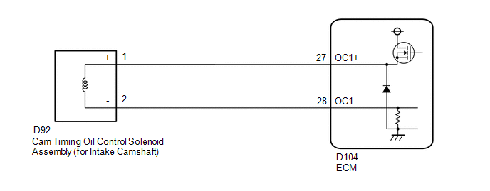
(c) Measure the resistance according to the value(s) in the table below.
Standard Resistance:
| Tester Connection | Condition | Specified Condition |
|---|---|---|
| D92-1(+) - D104-27(OC1+) | Always | Below 1 Ω |
| D92-2(-) - D104-28(OC1-) | Always | Below 1 Ω |
| D92-1(+) or D104-27(OC1+) - Body ground and other terminals | Always | 10 kΩ or higher |
| D92-2(-) or D104-28(OC1-) - Body ground and other terminals | Always | 10 kΩ or higher |
| OK |
 | REPLACE ECM |
| NG |
 | REPAIR OR REPLACE HARNESS OR CONNECTOR |
 VEHICLE CONTROL HISTORY (RoB)
VEHICLE CONTROL HISTORY (RoB) DESCRIPTION (SFI SYSTEM)
Vehicle Control History is a function that captures and stores ECU data when triggered by specific vehicle behavior...
 Camshaft Position "A" - Timing Over-Advanced or System Performance Bank 1 (P001100,P001200)
DESCRIPTION Refer to DTC P001013. Click here
DTC No. Detection Item DTC Detection Condition Trouble Area MIL Note P001100 Camshaft Position "A" - Timing Over-Advanced or System Performance Bank 1 Intake valve timing is stuck at a certain value when in the advance range (1 trip detection logic)...
Other information:
Toyota Yaris XP210 (2020-2026) Reapir and Service Manual: Crankshaft Position Sensor "A" No Signal (P033531)
DESCRIPTION This DTC is output when a malfunction has occurred in the engine pulse signal system from the ECM. DTC No. Detection Item DTC Detection Condition Trouble Area P033531 Crankshaft Position Sensor "A" No Signal Stereo component equalizer assembly detects malfunction in engine pulse signal system for 10 seconds or more continuously when engine speed is between 500 and 6000 rpm* Harness or connector ECM Stereo component equalizer assembly HINT: *: Malfunction monitoring is not performed under the following conditions, in order to prevent erroneous detection...
Toyota Yaris XP210 (2020-2026) Reapir and Service Manual: Terminals Of Ecu
TERMINALS OF ECU CHECK MULTIPLEX NETWORK MASTER SWITCH ASSEMBLY (a) Disconnect the L13 multiplex network master switch assembly connector. (b) Measure the voltage and resistance according to the value(s) in the table below. HINT: Measure the values on the wire harness side with the connector disconnected...
Categories
- Manuals Home
- Toyota Yaris Owners Manual
- Toyota Yaris Service Manual
- Auto Lock/Unlock Function
- How to use USB mode
- Fuel Gauge
- New on site
- Most important about car
Refueling
Before refueling, close all the doors, windows, and the liftgate/trunk lid, and switch the ignition OFF.
To open the fuel-filler lid, pull the remote fuel-filler lid release.
