Toyota Yaris: Sfi System / VEHICLE CONTROL HISTORY (RoB)
VEHICLE CONTROL HISTORY (RoB)
DESCRIPTION (SFI SYSTEM)
- Vehicle Control History is a function that captures and stores ECU data when triggered by specific vehicle behavior.
- If the customer states that the engine stalls or will not start, it may be possible to diagnose the cause of the malfunction by checking the vehicle history information and freeze frame data.
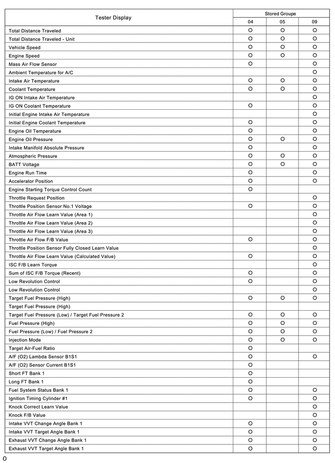
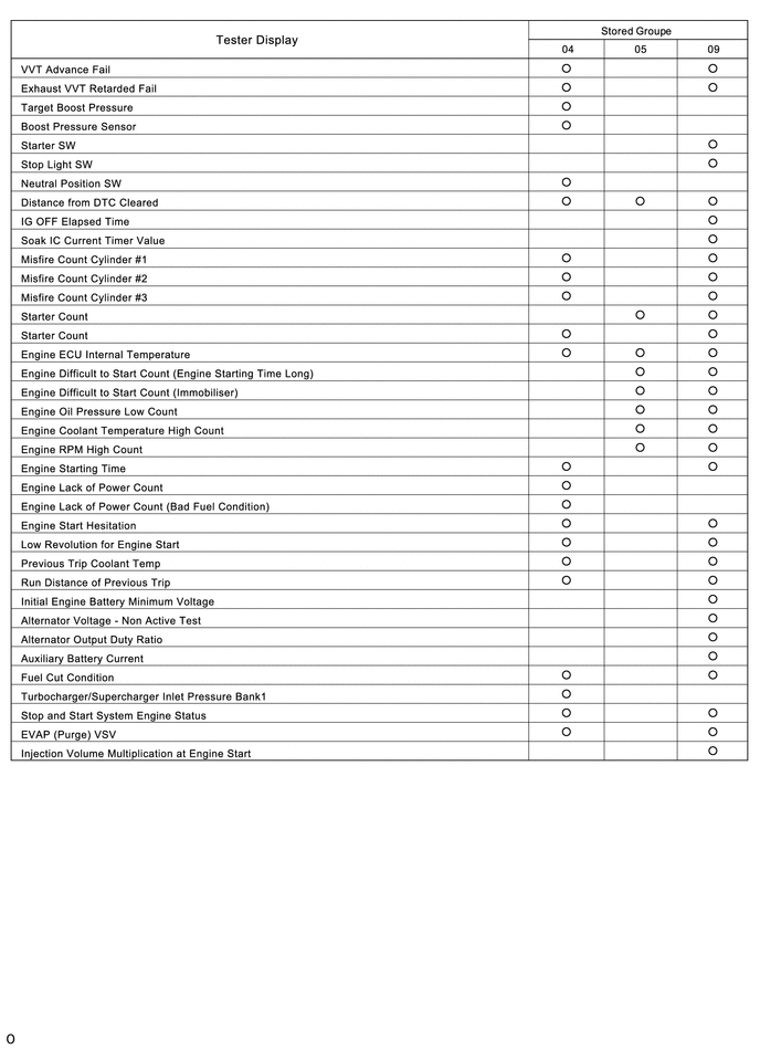
- The number of possible stored Freeze Frame Data sets, whether multi Freeze Frame Data is available, the number of freeze frame points, Freeze Frame Data items, the ECU internal range, etc., is different depending on the stored group.
-
The stored data items for Vehicle Control History Freeze Frame Data are different depending on the stored group. When the value of a data item does not change across all points, only the value of the detection point will be displayed. The contents of the Freeze Frame Data are almost the same as those of the Data List.
Click here

PRECAUTIONS (SFI SYSTEM)
- As Vehicle Control History may be overwritten whenever the trigger conditions are met, make sure to save Vehicle Control History before performing any inspections.
- As Vehicle Control History may be stored when performing an Active Test, learning, etc., make sure to clear the Vehicle Control History before returning the vehicle to the customer.
CHECK VEHICLE CONTROL HISTORY (SFI SYSTEM)
(a) Connect the GTS to the DLC3.
(b) Turn the ignition switch to ON.
(c) Turn the GTS on.
(d) Enter the following menus: Powertrain / Engine / Utility / Vehicle Control History (RoB).
Powertrain > Engine > Utility| Tester Display |
|---|
| Vehicle Control History (RoB) |
HINT:
It is also possible to display Vehicle Control History during the Health Check, if "Store All Data" is selected.
Vehicle Control History Item| Code | Item | Trigger Description | Stored Group | Reference Inspection Procedure | Link |
|---|---|---|---|---|---|
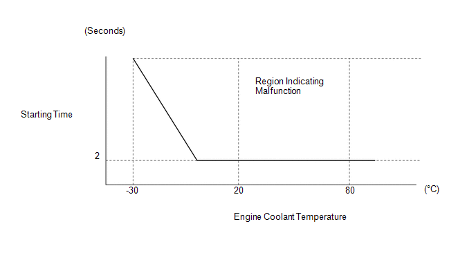
| X0810 | Engine Difficult to Start (Engine Starting Time Long) | Detection Condition (Engine Starting Time Long)
| 09 | Flowchart [Engine Difficult to Start] step 3 |
|
| The engine speed decreases or the engine stalls immediately after starting | |||||
| X0812 | Engine Difficult to Start (Immobiliser) | Engine difficult to start due to immobiliser | 09 | Flowchart [Engine Difficult to Start] step 3 |
|
| X0844 | Engine Lack of Power | Detection Condition (Engine Lack of Power)
| 04 | Flowchart [Lack of Power] step 3 |
|
| X0845 | Engine Lack of Power (Bad Fuel Condition) | Engine output is insufficient due to bad quality fuel (Fuel quality is bad due to fuel aging degradation, water intrusion or fuel additive) | 04 | Flowchart [Lack of Power] step 3 |
|
| X0850 | Engine Oil Pressure Low | The engine oil pressure is low | 05 | - | - |
| X0851 | Engine Coolant Temperature High | The engine coolant temperature is high (overheating) | 05 | - | - |
| X0852 | Engine RPM High | The engine speed is high (over revving) | 05 | - | - |
| X0854 | Engine Coolant Temperature High (Low Voltage) | The engine coolant temperature is high (overheating) due to a low engine water pump assembly voltage causing the engine water pump assembly to stop HINT: Only for vehicles equipped with an electric water pump (for engine). | 05 | - | - |
| XF01B | ECU Security Key Not Registered | ECU security key not updated | - | - |
|


 Stored Data
 | Stored Group | Number of Records | Number of Freeze Frame Points | Multi Freeze Frame Data Sampling Period | Note |
|---|---|---|---|---|
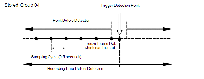
| 04 | 1 code HINT:
| 7 points (1 point at detection + 6 points before detection) HINT: When the value of a data item does not change across all points, only the value at the detection point will be displayed. | 0.5 seconds | The data can be cleared by using the GTS or by disconnecting the cable from the negative (-) auxiliary battery terminal. |
| 05 | 2 codes HINT:
| 1 point (multi freeze frame data not available) | - |
|
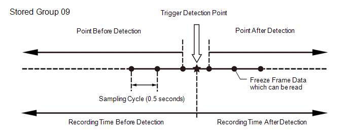
| 09 | 1 code HINT:
| 7 points (1 point at detection + 3 points before detection + 3 points after detection) HINT: When the value of a data item does not change across all points, only the value at the detection point will be displayed. | 0.5 seconds | The data can be cleared by using the GTS or by disconnecting the cable from the negative (-) auxiliary battery terminal. |
HINT:
- Multi Freeze Frame Data makes it possible to display the engine condition (ECU data) both before and after the trigger detection point.
- The number of available points differs depending on the stored group.
- When the value of a data item does not change across all points, only the value at the detection point will be displayed.
HINT:
Only 1 measurement point can be displayed for stored group 05 Freeze Frame Data.
CLEAR VEHICLE CONTROL HISTORY (SFI SYSTEM)
(a) Connect the GTS to the DLC3.
(b) Turn the ignition switch to ON.
(c) Turn the GTS on.
(d) Enter the following menus: Powertrain / Engine / Utility / Vehicle Control History (RoB) (Clear).
NOTICE:
By performing this procedure, all stored Vehicle Control History items will be cleared.
VEHICLE CONTROL HISTORY FREEZE FRAME DATA (SFI SYSTEM)
(a) Connect the GTS to the DLC3.
(b) Turn the ignition switch to ON.
(c) Turn the GTS on.
(d) Enter the following menus: Powertrain / Engine / Utility / Vehicle Control History (RoB).
Powertrain > Engine > Utility| Tester Display |
|---|
| Vehicle Control History (RoB) |
(e) Select a vehicle control history item to access the applicable freeze frame data.
(f) Check the freeze frame Data recorded with the Vehicle Control History.
VEHICLE CONTROL HISTORY (AIRBAG SYSTEM)
HINT:
A part of the control history can be confirmed using the vehicle control history.
Click here

 Diagnostic Trouble Code Chart
DIAGNOSTIC TROUBLE CODE CHART SFI System DTC No. Detection Item MIL Note Link P001013 A Camshaft Position Actuator Bank 1 Circuit Open Comes on SAE: P0010
P001100 Camshaft Position "A" - Timing Over-Advanced or System Performance Bank 1 Comes on SAE: P0011
P001200 Camshaft Position "A" - Timing Over-Retarded Bank 1 Comes on SAE: P0012
P001313 Camshaft Position "B" - Actuator Bank 1 Circuit Open Comes on SAE: P0013
P001400 Camshaft Position "B" - Timing Over-Advanced or System Performance Bank 1 Comes on SAE: P0014
P001500 Camshaft Position "B" - Timing Over-Retarded Bank 1 Comes on SAE: P0015
P001600 Crankshaft Position - Camshaft Position Correlation Bank 1 Sensor A Comes on SAE: P0016
P001700 Crankshaft Position - Camshaft Position Correlation Bank 1 Sensor B Comes on SAE: P0017
P003012 HO2S Heater Control Bank 1 Sensor 1 Circuit Short to Battery Comes on SAE: P0032
P003013 HO2S Heater Control Bank 1 Sensor 1 Circuit Open Comes on SAE: P0031
P003312 Turbocharger / Supercharger Bypass Valve "A" Control Circuit Short to Battery - SAE: P0035
P003314 Turbocharger / Supercharger Bypass Valve "A" Control Circuit Short to Ground or Open - SAE: P0034
P003612 HO2S Heater Control Circuit Bank 1 Sensor 2 Circuit Short to Battery Comes on SAE: P0038
P003613 A/F (O2) Heater Control Circuit Bank 1 Sensor 2 Circuit Open Comes on SAE: P0037
P006D62 Barometric Pressure - Turbocharger/Supercharger Inlet Pressure Correlation Bank 1 Signal Compare Failure - SAE: P006D
P007A11 Charge Air Cooler Temperature Sensor Bank 1 Circuit Short to Ground - SAE: P007C
P007A15 Charge Air Cooler Temperature Sensor Bank 1 Circuit Short to Battery or Open - SAE: P007D
P008700 Fuel Rail / System Pressure - Too Low Comes on SAE: P0087
P008800 Fuel Rail / System Pressure - Too High Comes on SAE: P0088
P008A00 Low Pressure Fuel System Pressure - Too Low - SAE: P008A
P008B00 Low Pressure Fuel System Pressure - Too High - SAE: P008B
P00CF62 Barometric Pressure - Turbocharger / Supercharger Boost Sensor "A" Signal Compare Failure Comes on SAE: P00CF
P010012 Mass or Volume Air Flow Sensor "A" Circuit Short to Battery Comes on SAE: P0103
P010014 Mass or Volume Air Flow Sensor "A" Circuit Short to Ground or Open Comes on SAE: P0102
P010511 Manifold Absolute Pressure / Barometric Pressure Sensor Circuit Short to Ground Comes on SAE: P0107
P010515 Manifold Absolute Pressure / Barometric Pressure Sensor Circuit Short to Battery or Open Comes on SAE: P0108
P011011 Intake Air Temperature Sensor 1 Bank 1 Circuit Short to Ground Comes on SAE: P0112
P011015 Intake Air Temperature Sensor 1 Bank 1 Circuit Short to Battery or Open Comes on SAE: P0113
P011511 Engine Coolant Temperature Sensor 1 Circuit Short to Ground Comes on SAE: P0117
P011515 Engine Coolant Temperature Sensor 1 Circuit Short to Battery or Open Comes on SAE: P0118
P01152A Engine Coolant Temperature Sensor 1 Signal Stuck in Range Comes on SAE: P0116
P012011 Throttle / Pedal Position Sensor / Switch "A" Circuit Short to Ground Comes on SAE: P0122
P012015 Throttle / Pedal Position Sensor / Switch "A" Circuit Short to Battery or Open Comes on SAE: P0123
P01201C Throttle / Pedal Position Sensor / Switch "A" Circuit Voltage Out of Range Comes on SAE: P0121
P012A11 Turbocharger/Supercharger Inlet Pressure Sensor "A" Circuit Low Circuit Short to Ground - SAE: P012C
P012A15 Turbocharger/Supercharger Inlet Pressure Sensor "A" Circuit High Circuit Short to Battery or Open - SAE: P012D
P013616 A/F (O2) Sensor Circuit Bank 1 Sensor 2 Circuit Current (Voltage) Below Threshold Comes on SAE: P0136
P017100 System Too Lean Bank 1 Comes on SAE: P0171
P017200 System Too Rich Bank 1 Comes on SAE: P0172
P019011 Fuel Rail Pressure Sensor "A" Circuit Short to Ground Comes on SAE: P0192
P019015 Fuel Rail Pressure Sensor "A" Circuit Short to Battery or Open Comes on SAE: P0193
P019511 Engine Oil Temperature Sensor Circuit Short to Ground - SAE: P0197
P019515 Engine Oil Temperature Sensor Circuit Short to Battery or Open - SAE: P0198
P020113 Cylinder 1 Injector "A" Circuit Open Comes on SAE: P0201
P020213 Cylinder 2 Injector "A" Circuit Open Comes on SAE: P0202
P020313 Cylinder 3 Injector "A" Circuit Open Comes on SAE: P0203
P022011 Throttle/Pedal Position Sensor/Switch "B" Circuit Short to Ground Comes on SAE: P0222
P022015 Throttle/Pedal Position Sensor/Switch "B" Circuit Short to Battery or Open Comes on SAE: P0223
P023400 Turbocharger/Supercharger "A" Overboost Condition - SAE: P0234
P023511 Turbocharger/Supercharger Boost Sensor "A" Circuit Short to Ground Comes on SAE: P0237
P023515 Turbocharger/Supercharger Boost Sensor "A" Circuit Short to Battery or Open Comes on SAE: P0238
P02351C Turbocharger/Supercharger Boost Sensor "A" Circuit Voltage Out of Range - SAE: P0236
P024313 Turbocharger/Supercharger Wastegate Solenoid "A" Circuit Open Does not come on SAE: P0243
P030000 Random/Multiple Cylinder Misfire Detected Comes on/Blinks* *: The MIL flashes when a catalyst-damaging misfire is detected...
 A Camshaft Position Actuator Bank 1 Circuit Open (P001013)
DESCRIPTION The Variable Valve Timing (VVT) system adjusts the intake valve timing to improve driveability. The engine oil pressure turns the VVT controller to adjust the valve timing...
Other information:
Toyota Yaris XP210 (2020-2026) Reapir and Service Manual: Components
COMPONENTS ILLUSTRATION *1 ROOF DRIP SIDE MOULDING LH *2 ROOF DRIP SIDE MOULDING RH *3 ROOF TOP MOULDING SUB-ASSEMBLY *4 ROOF ANTENNA ASSEMBLY WITH ANTENNA COVER *5 ROOF OUTSIDE COVER *6 SEAL *7 HOLDER - - N*m (kgf*cm, ft...
Toyota Yaris XP210 (2020-2026) Reapir and Service Manual: Removal
REMOVAL PROCEDURE 1. REMOVE LOWER STEERING COLUMN COVER Click here 2. REMOVE UPPER STEERING COLUMN COVER Click here 3. REMOVE TURN SIGNAL SWITCH (a) Remove the 2 screws. (b) Turn the steering wheel assembly to the left. (c) Using a screwdriver with its tip wrapped with protective tape, disengage the claw to remove the turn signal switch as shown in the illustration...
Categories
- Manuals Home
- Toyota Yaris Owners Manual
- Toyota Yaris Service Manual
- Auto Lock/Unlock Function
- Opening and Closing the Liftgate/Trunk Lid
- Engine Start Function When Key Battery is Dead
- New on site
- Most important about car
Liftgate/Trunk Lid
WARNING
Never allow a person to ride in the luggage compartment/trunk
Allowing a person to ride in the luggage compartment/trunk is dangerous. The person in the luggage compartment/trunk could be seriously injured or killed during sudden braking or a collision.
Do not drive with the liftgate/trunk lid open