Toyota Yaris: Sfi System / Throttle Actuator "A" Control Motor Circuit Current Below Threshold (P210018,P210019)
DESCRIPTION
The throttle actuator is operated by the ECM and opens and closes the throttle valve using gears.
The opening angle of the throttle valve is detected by the throttle position sensor, which is mounted on the throttle body with motor assembly. The throttle position sensor provides feedback to the ECM. This feedback allows the ECM to appropriately control the throttle actuator and monitor the throttle opening angle as the ECM responds to driver inputs.
| DTC No. | Detection Item | DTC Detection Condition | Trouble Area | MIL | Note |
|---|---|---|---|---|---|
| P210018 | Throttle Actuator "A" Control Motor Circuit Current Below Threshold | Both of the following conditions are met for 2 seconds or more (1 trip detection logic):
|
| Comes on | SAE: P2102 |
| P210019 | Throttle Actuator "A" Control Motor Circuit Current Above Threshold | Either of the following conditions is met (1 trip detection logic):
|
| Comes on | SAE: P2103 |
MONITOR DESCRIPTION
The ECM monitors the electrical current through the electronic actuator, and detects malfunctions and open circuits in the throttle actuator based on this value. If the current is outside the standard range, the ECM determines that there is a malfunction in the throttle actuator. In addition, if the throttle valve does not operate properly (for example, it is stuck open), the ECM will determine there is a malfunction, illuminate the MIL and store a DTC.
MONITOR STRATEGY
| Required Sensors/Components | Throttle actuator (throttle body with motor assembly) |
| Frequency of Operation | Continuous |
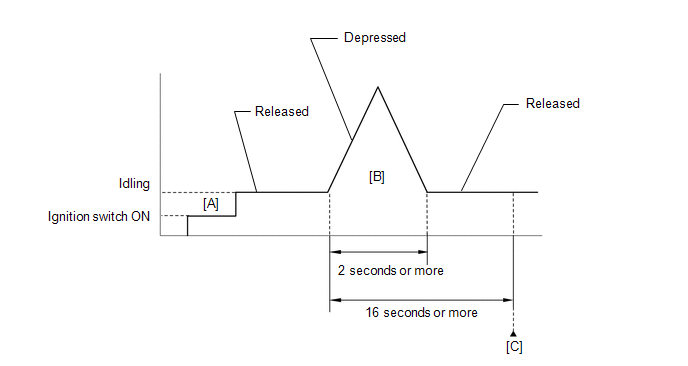
CONFIRMATION DRIVING PATTERN
- Connect the GTS to the DLC3.
- Turn the ignition switch to ON.
- Turn the GTS on.
- Clear the DTCs (even if no DTCs are stored, perform the clear DTC procedure).
- Turn the ignition switch off and wait for at least 30 seconds.
- Turn the ignition switch to ON [A].
- Turn the GTS on.
- Start the engine.
- With the vehicle stationary, fully depress the accelerator pedal and quickly release it [B].
- Check that 16 seconds or more have elapsed since the accelerator pedal was first depressed.
- Enter the following menus: Powertrain / Engine / Trouble Codes [C].
-
Read the pending DTCs.
HINT:
- If a pending DTC is output, the system is malfunctioning.
- If a pending DTC is not output, perform the following procedure.
- Enter the following menus: Powertrain / Engine / Utility / All Readiness.
- Input the DTC: P210018 or P210019
-
Check the DTC judgment result.
GTS Display
Description
NORMAL
- DTC judgment completed
- System normal
ABNORMAL
- DTC judgment completed
- System abnormal
INCOMPLETE
- DTC judgment not completed
- Perform driving pattern after confirming DTC enabling conditions
HINT:
- If the judgment result is NORMAL, the system is normal.
- If the judgment result is ABNORMAL, the system is malfunctioning.
- If the judgment result is INCOMPLETE, perform steps [B] through [C] again.
FAIL-SAFE
When these DTCs are stored, the ECM enters fail-safe mode. During fail-safe mode, the ECM cuts the current to the throttle actuator, and the throttle valve is returned to a 8° throttle valve opening angle by the return spring. The ECM then adjusts the engine output by controlling the fuel injection (intermittent fuel-cut) and ignition timing, in accordance with the accelerator pedal opening angle, to allow the vehicle to continue running at a minimal speed. If the accelerator pedal is depressed firmly and gently, the vehicle can be driven slowly.
Fail-safe mode continues until a pass condition is detected, and the ignition switch is turned off.
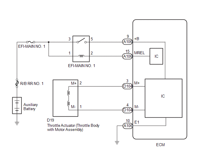
WIRING DIAGRAM
CAUTION / NOTICE / HINT
HINT:
- The throttle actuator current (Throttle Motor Current and Throttle2 Throttle Motor Current) and the throttle actuator duty ratio (Throttle Motor Duty Ratio (Open), Throttle Motor Duty Ratio (Close), Throttle2 Throttle Motor Duty Ratio (Open) and Throttle2 Throttle Motor Duty Ratio (Close)) can be read using the GTS. However, the ECM shuts off the throttle actuator current when the electronic throttle control system malfunctions.
- Read Freeze Frame Data using the GTS. The ECM records vehicle and driving condition information as Freeze Frame Data the moment a DTC is stored. When troubleshooting, Freeze Frame Data can help determine if the vehicle was moving or stationary, if the engine was warmed up or not, if the air fuel ratio was lean or rich, and other data from the time the malfunction occurred.
PROCEDURE
| 1. | INSPECT THROTTLE BODY WITH MOTOR ASSEMBLY (RESISTANCE OF THROTTLE ACTUATOR) |
Click here

HINT:
-
When cleaning or replacing one throttle body with motor assembly, clean the other throttle body with motor assembly.
Click here

-
Perform "Inspection After Repair" after replacing the throttle body with motor assembly.
Click here

| NG |
 | REPLACE THROTTLE BODY WITH MOTOR ASSEMBLY |
|

| 2. | CHECK HARNESS AND CONNECTOR (THROTTLE BODY WITH MOTOR ASSEMBLY - ECM) |
(a) Disconnect the throttle body with motor assembly connector.
(b) Disconnect the ECM connector.
(c) Measure the resistance according to the value(s) in the table below.
Standard Resistance:
| Tester Connection | Condition | Specified Condition |
|---|---|---|
| D19-2(M+) - D104-3(M+) | Always | Below 1 Ω |
| D19-1(M-) - D104-4(M-) | Always | Below 1 Ω |
| D19-2(M+) or D104-3(M+) - Body ground and other terminals | Always | 10 kΩ or higher |
| D19-1(M-) or D104-4(M-) - Body ground and other terminals | Always | 10 kΩ or higher |
| NG |
 | REPAIR OR REPLACE HARNESS OR CONNECTOR |
|

| 3. | INSPECT THROTTLE BODY WITH MOTOR ASSEMBLY (VISUALLY CHECK THROTTLE VALVE) |
(a) Check for foreign matter between the throttle valve and the housing.
OK:
No foreign matter between the throttle valve and housing.
HINT:
-
When cleaning or replacing one throttle body with motor assembly, clean the other throttle body with motor assembly.
Click here

-
Perform "Inspection After Repair" after cleaning the throttle body with motor assembly.
Click here

| NG |
 | REMOVE FOREIGN MATTER AND CLEAN THROTTLE BODY WITH MOTOR ASSEMBLY |
|

| 4. | INSPECT THROTTLE BODY WITH MOTOR ASSEMBLY (THROTTLE VALVE) |
(a) Check if the throttle valve opens and closes smoothly.
OK:
Throttle valve opens and closes smoothly.
HINT:
-
When cleaning or replacing one throttle body with motor assembly, clean the other throttle body with motor assembly.
Click here

-
Perform "Inspection After Repair" after replacing the throttle body with motor assembly.
Click here

| OK |
 | REPLACE ECM |
| NG |
 | REPLACE THROTTLE BODY WITH MOTOR ASSEMBLY |
 Actuator Cut Circuit Stuck Off (P16B09F)
MONITOR DESCRIPTION The ECM monitors the operation of the throttle actuator. When a malfunction is detected in the throttle actuator cut circuit immediately after the ignition switch is turned off, the ECM illuminates the MIL and stores a DTC...
 Throttle/Pedal Position Sensor "A" Minimum Stop Performance (P210900)
DESCRIPTION The idle speed is controlled by the Electronic Throttle Control System (ETCS). The ETCS is comprised of a throttle actuator, which operates the throttle valve, and a throttle position sensor, which detects the opening amount of the throttle valve...
Other information:
Toyota Yaris XP210 (2020-2025) Reapir and Service Manual: Components
COMPONENTS ILLUSTRATION *1 NO. 1 SIDE DEFROSTER NOZZLE DUCT *2 NO. 2 SIDE DEFROSTER NOZZLE DUCT *3 ANTENNA CORD SUB-ASSEMBLY - - ILLUSTRATION *1 NO. 2 ANTENNA CORD SUB-ASSEMBLY *2 NO. 8 ANTENNA CORD SUB-ASSEMBLY N*m (kgf*cm, ft...
Toyota Yaris XP210 (2020-2025) Reapir and Service Manual: Charging Failure
PROCEDURE 1. CHECK GENERATOR PULLEY WITH CLUTCH (ON-VEHICLE INSPECTION) (a) Start the engine and visually check that the generator rotor assembly (fan) in the generator assembly is operating. OK: The generator rotor assembly (fan) is operating...
Categories
- Manuals Home
- Toyota Yaris Owners Manual
- Toyota Yaris Service Manual
- Immobilizer System
- Auto Lock/Unlock Function
- To Set Speed
- New on site
- Most important about car
Break-In Period
No special break-in is necessary, but a few precautions in the first 600 miles (1,000 km) may add to the performance, economy, and life of the vehicle.
Do not race the engine. Do not maintain one constant speed, either slow or fast, for a long period of time. Do not drive constantly at full-throttle or high engine rpm for extended periods of time. Avoid unnecessary hard stops. Avoid full-throttle starts.