Toyota Yaris: Lighting System / Terminals Of Ecu
TERMINALS OF ECU
CHECK MAIN BODY ECU (MULTIPLEX NETWORK BODY ECU) AND POWER DISTRIBUTION BOX ASSEMBLY
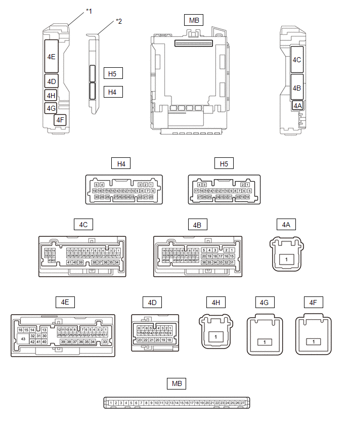
| *1 | Power Distribution Box Assembly | *2 | Main Body ECU (Multiplex Network Body ECU) |
(a) Remove the main body ECU (multiplex network body ECU) from the power distribution box assembly.
Click here

(b) Connect the power distribution box assembly connectors.
(c) Measure the voltage and resistance according to the value(s) in the table below.
| Terminal No. (Symbol) | Terminal Description | Condition | Specified Condition |
|---|---|---|---|
| MB-13 (GND1) - Body ground | Ground | Always | Below 1 Ω |
| MB-14 (GND2) - Body ground | Ground | Always | Below 1 Ω |
| MB-26 (BECU) - Body ground | Auxiliary battery power supply | Ignition switch off | 11 to 14 V |
| MB-27 (IGR) - Body ground | Ignition power supply | Ignition switch off | Below 1 V |
| Ignition switch ON | 11 to 14 V |
(d) Install the main body ECU (multiplex network body ECU).
Click here

(e) Connect the power distribution box assembly and main body ECU (multiplex network body ECU) connectors.
(f) Measure the voltage and check for pulses according to the value(s) in the table below.
| Terminal No. (Symbol) | Terminal Description | Condition | Specified Condition |
|---|---|---|---|
| 4F-1 - Body ground | DOME CUT relay drive power supply | Ignition switch off | 11 to 14 V |
| 4E-3 - Body ground | Front door courtesy light switch (LH) signal | Front door LH open | Below 1 V |
| Front door LH closed | 4.7 to 5.3 V | ||
| 4E-5 - Body ground | Front door courtesy light switch (RH) signal | Front door RH open | Below 1 V |
| Front door RH closed | 4.7 to 5.3 V | ||
| 4C-1 - Body ground | Each instrument panel illumination power supply | Light control switch in neither tail nor head position | Below 1 V |
| Light control switch in tail or head position | 11 to 14 V | ||
| 4C-4 - Body ground | Interior light power supply | DOME CUT relay off | 11 to 14 V |
| DOME CUT relay on | Below 1 V | ||
| H4-5 (ILE) - Body ground | Illuminated entry system drive output | Illuminated entry system inactive | 11 to 14 V |
| Illuminated entry system operation | Below 1 V | ||
| 4E-9 - Body ground | Multiplex network master switch assembly illumination light power supply | Multiplex network master switch assembly illumination light off | Below 1 V |
| Multiplex network master switch assembly illumination light on | 11 to 14 V | ||
| 4E-2 - Body ground | Back door courtesy light switch signal | Back door locked | Pulse generation |
| Back door unlocked | Below 1 V | ||
| H4-9 (LSFL) - Body ground | Front door LH unlock detection switch input | Front door LH locked | Pulse generation |
| Front door LH unlocked | Below 1 V | ||
| H4-3 (LSFR) - Body ground | Front door RH unlock detection switch input | Front door RH locked | Pulse generation |
| Front door RH unlocked | Below 1 V |
NOTICE:
*: If the low beam headlights or clearance lights illuminate when the ignition switch is turned ON, shine a light on the automatic light control sensor to turn the low beam headlights off before operating the headlight dimmer switch.
CHECK CERTIFICATION ECU (SMART KEY ECU ASSEMBLY)
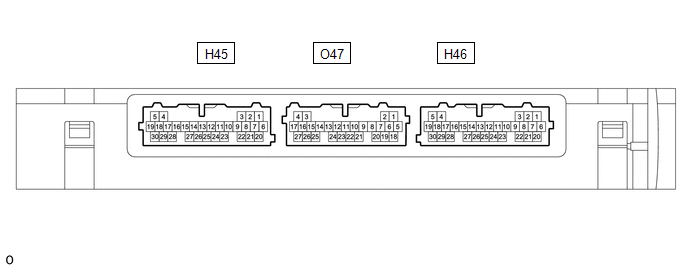
(a) Measure the voltage according to the value(s) in the table below.
| Terminal No. (Symbol) | Terminal Description | Condition | Specified Condition |
|---|---|---|---|
| H46-20 (SWIL) - H46-30 (AGND) | Push start switch illumination drive output | Push start switch illumination off | Below 1 V |
| Push start switch illumination on | 11 to 14 V |
 Problem Symptoms Table
PROBLEM SYMPTOMS TABLE NOTICE: Before replacing the main body ECU (multiplex network body ECU) or certification ECU (smart key ECU assembly), refer to Registration...
 Diagnosis System
DIAGNOSIS SYSTEM DESCRIPTION (a) Lighting system data and Diagnostic Trouble Codes (DTCs) can be read from the Data Link Connector 3 (DLC3) of the vehicle...
Other information:
Toyota Yaris XP210 (2020-2026) Reapir and Service Manual: ABS Pump Motor Actuator Stuck (C142771)
DESCRIPTION DTC No. Detection Item DTC Detection Condition Trouble Area DTC Output from C142771 ABS Pump Motor Actuator Stuck Actuator pump motor does not operate properly. Wire harness and connector Brake actuator assembly (Pump motor) Brake actuator assembly (Pump motor circuit) Brake WIRING DIAGRAM Refer to DTC C052C13...
Toyota Yaris XP210 (2020-2026) Reapir and Service Manual: Components
C..
Categories
- Manuals Home
- Toyota Yaris Owners Manual
- Toyota Yaris Service Manual
- Auto Lock/Unlock Function
- Brake System Control Module "A" System Voltage System Voltage Low (C137BA2)
- Battery Monitor Module General Electrical Failure (P058A01)
- New on site
- Most important about car
Key Suspend Function
If a key is left in the vehicle, the functions of the key left in the vehicle are temporarily suspended to prevent theft of the vehicle.
To restore the functions, press the unlock button on the functions-suspended key in the vehicle.