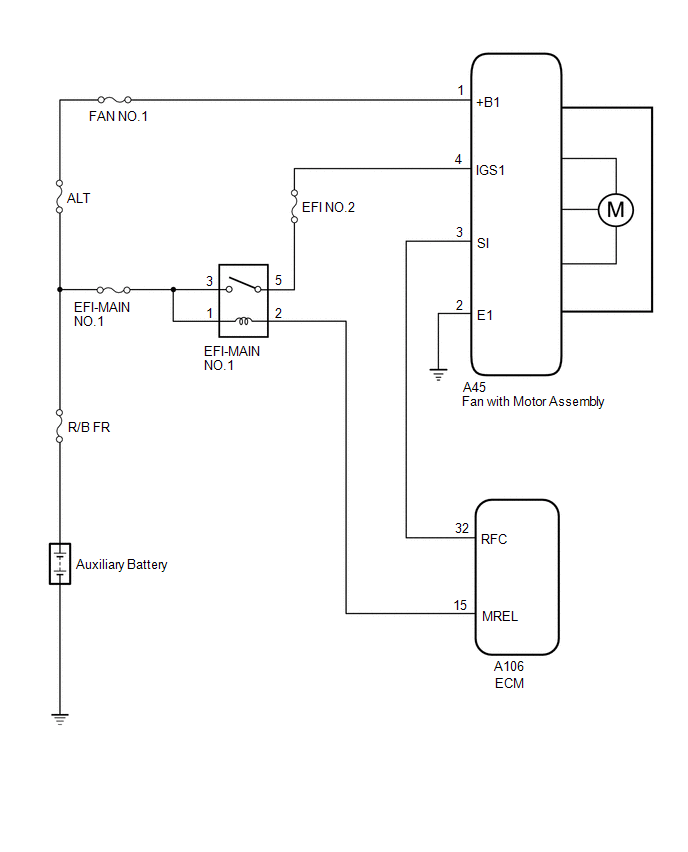
Toyota Yaris: Cooling Fan System / System Diagram
SYSTEM DIAGRAM
 Parts Location
P..
 On-vehicle Inspection
ON-VEHICLE INSPECTION PROCEDURE 1. INSPECT COOLING FAN SYSTEM CAUTION: To prevent injury due to contact with an operating cooling fan, keep your hands and clothing away from the cooling fan when inspecting the cooling fan system...
Other information:
Toyota Yaris XP210 (2020-2026) Reapir and Service Manual: Parts Location
PARTS LOCATION ILLUSTRATION *1 SEMICONDUCTOR POWER INTEGRATION ECU *2 ENGINE ROOM RELAY BLOCK - STD P/I NO. 1 FUSE - INP STD NO. 1-1 FUSE - WASHER FUSE *3 LIGHT CONTROL LED ECU RH *4 LIGHT CONTROL LED ECU LH ILLUSTRATION *1 MAIN BODY ECU (MULTIPLEX NETWORK BODY ECU) *2 POWER DISTRIBUTION BOX ASSEMBLY - ECU-IGR NO...
Toyota Yaris XP210 (2020-2026) Reapir and Service Manual: Active Noise Control ECU Communication Stop Mode
DESCRIPTION Detection Item Symptom Trouble Area Active Noise Control ECU Communication Stop Mode Communication stop history for "Active Noise Control" is indicated on the "Communication Bus Check (Detail)" screen of the GTS. (The Lost Communication Time value for "Active Noise Control" is 6 or more...
Categories
- Manuals Home
- Toyota Yaris Owners Manual
- Toyota Yaris Service Manual
- Removal
- To Set Speed
- Fuel Gauge
- New on site
- Most important about car
Break-In Period
No special break-in is necessary, but a few precautions in the first 600 miles (1,000 km) may add to the performance, economy, and life of the vehicle.
Do not race the engine. Do not maintain one constant speed, either slow or fast, for a long period of time. Do not drive constantly at full-throttle or high engine rpm for extended periods of time. Avoid unnecessary hard stops. Avoid full-throttle starts.
Copyright © 2026 www.toyaris4.com