Toyota Yaris: Cooling Fan System / On-vehicle Inspection
ON-VEHICLE INSPECTION
PROCEDURE
1. INSPECT COOLING FAN SYSTEM
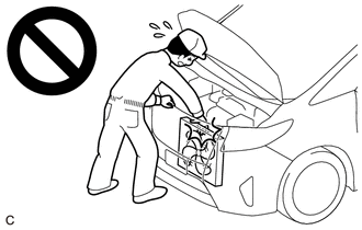
CAUTION:
To prevent injury due to contact with an operating cooling fan, keep your hands and clothing away from the cooling fan when inspecting the cooling fan system.
(a) Connect the GTS to the DLC3.
(b) Turn the ignition switch to ON.
(c) Turn the GTS on.
(d) Enter the following menus: Powertrain / Engine / Active Test / Control the Engine Cooling Fan Duty Ratio.
Powertrain > Engine > Active Test| Tester Display |
|---|
| Control the Engine Cooling Fan Duty Ratio |
(e) Check the operation of the cooling fan while operating it using the GTS.
If the cooling fan motor does not operate, check the cooling fan circuit.
Click here

 System Diagram
S..
 Cooling Fan Circuit
DESCRIPTION The ECM calculates an appropriate cooling fan speed based on the engine coolant temperature, air conditioning switch status, refrigerant pressure, engine speed and vehicle speed, and sends a signal to the cooling fan ECU (fan with motor assembly)...
Other information:
Toyota Yaris XP210 (2020-2026) Reapir and Service Manual: VEHICLE CONTROL HISTORY (RoB)
VEHICLE CONTROL HISTORY (RoB) NOTICE: Replacing or repairing related components may cause vehicle control history codes to be stored. When checking the vehicle control history, make sure to record the output histories. Then, clear the histories and recheck the output histories again...
Toyota Yaris XP210 (2020-2026) Reapir and Service Manual: Components
COMPONENTS ILLUSTRATION *1 WATER GUARD PLATE RH *2 NO. 1 FRONT VENTILATOR SEAL *3 OUTER COWL TOP PANEL SUB-ASSEMBLY - - N*m (kgf*cm, ft.*lbf): Specified torque - - ILLUSTRATION *1 DASH PANEL HEAT INSULATOR *2 NO...
Categories
- Manuals Home
- Toyota Yaris Owners Manual
- Toyota Yaris Service Manual
- Power Integration No.1 System Missing Message (B235287,B235587,B235787-B235987)
- How to use USB mode
- Brake System Control Module "A" System Voltage System Voltage Low (C137BA2)
- New on site
- Most important about car
Supplemental Restraint System (SRS) Precautions
The front and side supplemental restraint systems (SRS) include different types of air bags. Please verify the different types of air bags which are equipped on your vehicle by locating the “SRS AIRBAG” location indicators. These indicators are visible in the area where the air bags are installed.
The air bags are installed in the following locations:
The steering wheel hub (driver air bag) The front passenger dashboard (front passenger air bag) The outboard sides of the front seatbacks (side air bags) The front and rear window pillars, and the roof edge along both sides (curtain air bags)