Toyota Yaris: Cooling Fan System / Parts Location
PARTS LOCATION
ILLUSTRATION
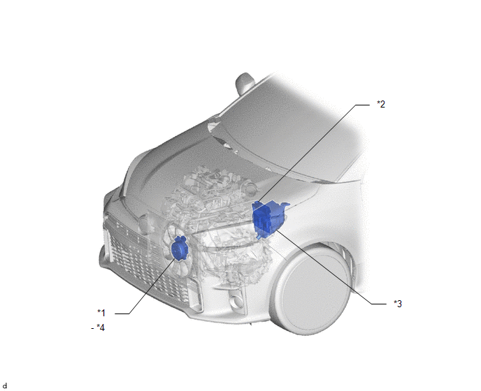
| *1 | COOLING FAN MOTOR | *2 | ECM |
| *3 | ENGINE ROOM RELAY BLOCK - EFI-MAIN NO.1 RELAY | *4 | COOLING FAN ECU |

 System Diagram
S..
Other information:
Toyota Yaris XP210 (2020-2026) Reapir and Service Manual: 4WD/AWD Front/Rear Range Actuator Control Circuit Performance Circuit Voltage Out of Range (C05F51C)
DESCRIPTION When a malfunction has occurred in the AWD coupling solenoid system, the AWD ECU assembly stores DTC C05F51C. DTC No. Detection Item DTC Detection Condition Trouble Area Warning Indicate Memory C05F51C 4WD/AWD Front/Rear Range Actuator Control Circuit Performance Circuit Voltage Out of Range When the IG1 terminal voltage is 9...
Toyota Yaris XP210 (2020-2026) Reapir and Service Manual: A/C Switch Indicator does not Turn On
DESCRIPTION If none of the switch indicators on the air conditioning control assembly illuminate, the following factors may be the cause. Symptom Factor A/C switch indicator does not illuminate Vehicle control history (RoB) Air conditioning amplifier assembly malfunction Air conditioning control assembly malfunction A/C switch malfunction A/C switch indicator malfunction (including when indicator turned off without switch operation) Servo motor initialization (incomplete) Mechanical locking of damper and damper link Refrigerant pressure is extremely low Low detected ambient temperature (including thermistor assembly malfunction) PROCEDURE 1...
Categories
- Manuals Home
- Toyota Yaris Owners Manual
- Toyota Yaris Service Manual
- Brake System Control Module "A" System Voltage System Voltage Low (C137BA2)
- Diagnostic Trouble Code Chart
- Immobilizer System
- New on site
- Most important about car
Fuel Gauge
The fuel gauge shows approximately how much fuel is remaining in the tank when the ignition is switched ON. We recommend keeping the tank over 1/4 full.

Copyright © 2026 www.toyaris4.com