Toyota Yaris: G16e-gts (engine Control) / Accelerator Pedal
Components
COMPONENTS
ILLUSTRATION
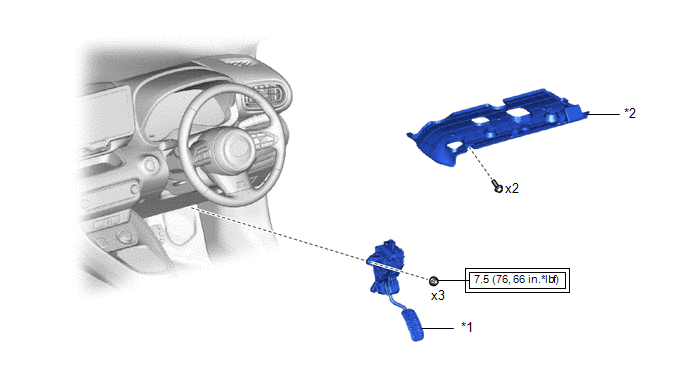
| *1 | ACCELERATOR PEDAL SENSOR ASSEMBLY | *2 | NO. 1 INSTRUMENT PANEL UNDER COVER SUB-ASSEMBLY |
 | Tightening torque for "Major areas involving basic vehicle performance such as moving/turning/stopping" : N*m (kgf*cm, ft.*lbf) | - | - |
On-vehicle Inspection
ON-VEHICLE INSPECTION
PROCEDURE
1. INSPECT ACCELERATOR PEDAL SENSOR ASSEMBLY
(a) Connect the GTS to the DLC3.
(b) Turn the ignition switch on (IG).
(c) Turn the GTS on.
(d) Enter the following menus: Powertrain / Engine / Data List / Accel Position Sensor No. 1 Voltage and Accel Position Sensor No. 2 Voltage.
Powertrain > Engine > Data List| Tester Display |
|---|
| Accelerator Position Sensor No.1 Voltage |
| Accelerator Position Sensor No.2 Voltage |
(e) Read the values displayed on the GTS.
Standard Voltage:
| Tester Display | Condition | Specified Condition |
|---|---|---|
| Accelerator Position Sensor No. 1 Voltage | Accelerator pedal is fully released | 0.5 to 1.1 V |
| Accelerator pedal is fully depressed | 2.6 to 4.5 V | |
| Accelerator Position Sensor No. 2 Voltage | Accelerator pedal is fully released | 1.2 to 2.0 V |
| Accelerator pedal is fully depressed | 3.4 to 4.75 V |
If the result is not as specified, check the accelerator pedal sensor assembly, wire harness and ECM.
Removal
REMOVAL
PROCEDURE
1. REMOVE NO. 1 INSTRUMENT PANEL UNDER COVER SUB-ASSEMBLY
Click here

2. REMOVE ACCELERATOR PEDAL SENSOR ASSEMBLY
NOTICE:
- Avoid physical shock to the accelerator pedal sensor assembly.
- Do not disassemble the accelerator pedal sensor assembly.
- The accelerator pedal sensor assembly does not require lubrication.
- Do not apply oil or other lubricants to the accelerator pedal sensor assembly. If applied, the accelerator pedal sensor assembly must be replaced.
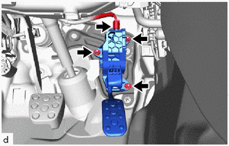
(a) for LHD:
(1) Disconnect the accelerator pedal sensor assembly connector.
(2) Remove the 3 nuts and accelerator pedal sensor assembly.
NOTICE:
If the accelerator pedal sensor assembly has been struck or dropped, replace it.
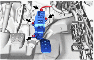
| (b) for RHD: (1) Disconnect the accelerator pedal sensor assembly connector. (2) Remove the 3 nuts and accelerator pedal sensor assembly. NOTICE: If the accelerator pedal sensor assembly has been struck or dropped, replace it. |
|
Installation
INSTALLATION
PROCEDURE
1. INSTALL ACCELERATOR PEDAL SENSOR ASSEMBLY
NOTICE:
- Avoid physical shock to the accelerator pedal sensor assembly.
- Do not disassemble the accelerator pedal sensor assembly.
- The accelerator pedal sensor assembly does not require lubrication.
- Do not apply oil or other lubricants to the accelerator pedal sensor assembly. If applied, the accelerator pedal sensor assembly must be replaced.
(a) for LHD:
(1) Install the accelerator pedal sensor assembly with the 3 nuts.
Torque:
7.5 N·m {76 kgf·cm, 66 in·lbf}
NOTICE:
If the accelerator pedal sensor assembly has been struck or dropped, replace it.
(2) Connect the accelerator pedal sensor assembly connector.
(b) for RHD:
(1) Install the accelerator pedal sensor assembly with the 3 nuts.
Torque:
7.5 N·m {76 kgf·cm, 66 in·lbf}
NOTICE:
If the accelerator pedal sensor assembly has been struck or dropped, replace it.
(2) Connect the accelerator pedal sensor assembly connector.
2. INSTALL NO. 1 INSTRUMENT PANEL UNDER COVER SUB-ASSEMBLY
Click here


Other information:
Toyota Yaris XP210 (2020-2026) Reapir and Service Manual: Backup Boost Converter Circuit
DESCRIPTION A backup boost converter is built into the engine stop and start ECU. The backup boost converter helps maintain the power source voltage when the engine is restarted by stop and start control. This prevents various functions such as the audio and visual system from malfunctioning if the power source voltage drops due to the auxiliary battery voltage dropping when the engine is restarted by stop and start control...
Toyota Yaris XP210 (2020-2026) Owner's Manual: Voice Recognition
In this section, the basic operation of the voice recognition is explained. Activating Voice Recognition Press the talk button. Ending Voice Recognition Use one of the following methods: Press the hang-up button. Say, “Cancel”. Operate the commander switch or the center display (only when vehicle is stopped)...
Categories
- Manuals Home
- Toyota Yaris Owners Manual
- Toyota Yaris Service Manual
- Headlights
- Power Integration No.1 System Missing Message (B235287,B235587,B235787-B235987)
- Battery Monitor Module General Electrical Failure (P058A01)
- New on site
- Most important about car
Supplemental Restraint System (SRS) Precautions
The front and side supplemental restraint systems (SRS) include different types of air bags. Please verify the different types of air bags which are equipped on your vehicle by locating the “SRS AIRBAG” location indicators. These indicators are visible in the area where the air bags are installed.
The air bags are installed in the following locations:
The steering wheel hub (driver air bag) The front passenger dashboard (front passenger air bag) The outboard sides of the front seatbacks (side air bags) The front and rear window pillars, and the roof edge along both sides (curtain air bags)