Toyota Yaris: Pre-collision System / System Diagram
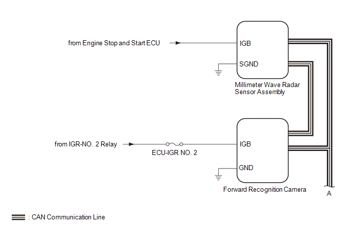
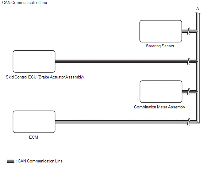
SYSTEM DIAGRAM
 Parts Location
PARTS LOCATION ILLUSTRATION
*1 FORWARD RECOGNITION CAMERA *2 MILLIMETER WAVE RADAR SENSOR ASSEMBLY *3 BRAKE ACTUATOR ASSEMBLY - SKID CONTROL ECU *4 ECM ILLUSTRATION
*1 COMBINATION METER ASSEMBLY - MULTI-INFORMATION DISPLAY - PCS WARNING LIGHT *2 STEERING SENSOR *3 POWER DISTRIBUTION BOX ASSEMBLY - ECU-IGR NO...
 How To Proceed With Troubleshooting
CAUTION / NOTICE / HINT HINT:
Use the following procedure to troubleshoot the pre-collision system.
*: Use the GTS.
PROCEDURE 1. VEHICLE BROUGHT TO WORKSHOP
NEXT
2...
Other information:
Toyota Yaris XP210 (2020-2026) Owner's Manual: Locking, Unlocking with Smart Key and Door-Lock Switch
Locking, Unlocking with Smart Key All doors and the liftgate can be locked/unlocked by operating the keyless entry system smart key, refer to Keyless Entry System Locking, Unlocking with Door-Lock Switch All doors and the liftgate lock automatically when the lock side is pressed...
Toyota Yaris XP210 (2020-2026) Reapir and Service Manual: Barometric Pressure - Turbocharger / Supercharger Boost Sensor "A" Signal Compare Failure (P00CF62)
DESCRIPTION At ignition switch to ON or during idling, the No. 2 turbo pressure sensor and the atmospheric pressure sensor built into the ECM are at atmospheric pressure and their outputs match. DTC No. Detection Item DTC Detection Condition Trouble Area MIL Note P00CF62 Barometric Pressure - Turbocharger / Supercharger Boost Sensor "A" Signal Compare Failure 15 kPa [2...
Categories
- Manuals Home
- Toyota Yaris Owners Manual
- Toyota Yaris Service Manual
- Opening and Closing the Liftgate/Trunk Lid
- How to connect USB port/Auxiliary jack
- Headlights
- New on site
- Most important about car
Turning the Engine Off
Stop the vehicle completely. Manual transaxle: Shift into neutral and set the parking brake.Automatic transaxle: Shift the selector lever to the P position and set the parking brake.
Press the push button start to turn off the engine. The ignition position is off.
Copyright © 2026 www.toyaris4.com