Toyota Yaris: Power Door Lock Control System / System Diagram
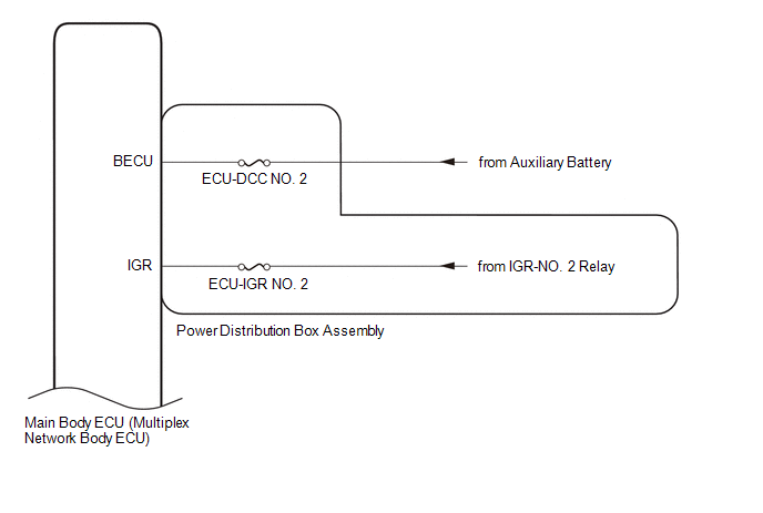
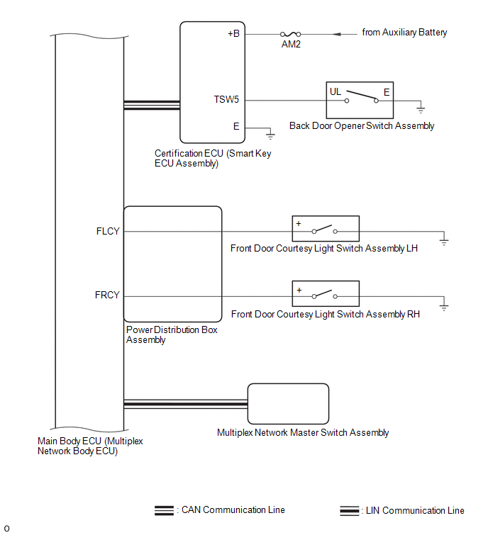
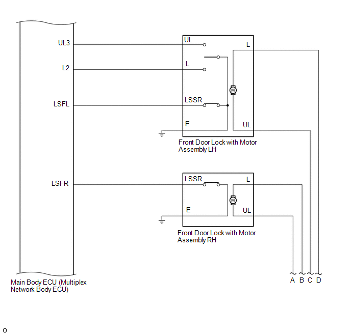
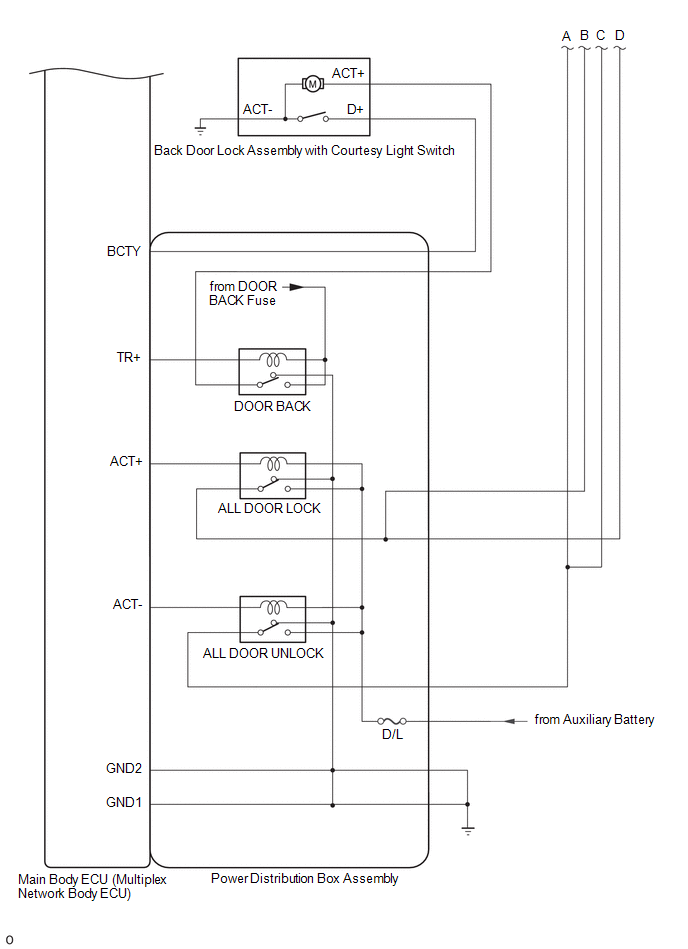
SYSTEM DIAGRAM
 Parts Location
PARTS LOCATION ILLUSTRATION
*1 FRONT DOOR LOCK WITH MOTOR ASSEMBLY RH *2 FRONT DOOR COURTESY LIGHT SWITCH ASSEMBLY RH *3 FRONT DOOR LOCK WITH MOTOR ASSEMBLY LH *4 FRONT DOOR COURTESY LIGHT SWITCH ASSEMBLY LH *5 BACK DOOR OPENER SWITCH ASSEMBLY *6 BACK DOOR LOCK ASSEMBLY WITH COURTESY LIGHT SWITCH ILLUSTRATION
*1 MULTIPLEX NETWORK MASTER SWITCH ASSEMBLY *2 DOOR CONTROL SWITCH *3 MAIN BODY ECU (MULTIPLEX NETWORK BODY ECU) *4 POWER DISTRIBUTION BOX ASSEMBLY - ECU-IGR NO...
 How To Proceed With Troubleshooting
CAUTION / NOTICE / HINT HINT:
Use the following procedure to troubleshoot the power door lock control system.
*: Use the GTS.
PROCEDURE 1. VEHICLE BROUGHT TO WORKSHOP
NEXT
2...
Other information:
Toyota Yaris XP210 (2020-2026) Reapir and Service Manual: Fuel Rail Pressure Sensor (Low) Circuit Short to Ground (P107A11)
DESCRIPTION The No. 2 fuel pressure sensor (for low pressure side) replaces the fuel pressure with electrical signals and outputs them to the ECM. The ECM controls the optimal fuel pressure for the operation conditions to reduce the fuel pump power consumption and improve fuel economy...
Toyota Yaris XP210 (2020-2026) Reapir and Service Manual: Installation
INSTALLATION CAUTION / NOTICE / HINT HINT: Use the same procedure for the RH and LH sides. The procedure listed below is for the LH side. PROCEDURE 1. INSTALL FRONT NO. 1 SPEAKER BRACKET (a) Engage the hooks to install the front No. 1 speaker bracket...
Categories
- Manuals Home
- Toyota Yaris Owners Manual
- Toyota Yaris Service Manual
- Engine Start Function When Key Battery is Dead
- Opening and Closing the Liftgate/Trunk Lid
- Brake System Control Module "A" System Voltage System Voltage Low (C137BA2)
- New on site
- Most important about car
Fuel Gauge
The fuel gauge shows approximately how much fuel is remaining in the tank when the ignition is switched ON. We recommend keeping the tank over 1/4 full.

Copyright © 2026 www.toyaris4.com