Toyota Yaris: Steering Column / Steering System
Precaution
PRECAUTION
HANDLING PRECAUTIONS FOR STEERING SYSTEM
(a) Care must be taken when replacing parts. Incorrect replacement may affect the performance of the steering system and result in a driving hazard.
HANDLING PRECAUTIONS FOR SRS AIRBAG SYSTEM
(a) This vehicle is equipped with a Supplemental Restraint System (SRS). Failure to carry out service operations in the correct sequence could cause the SRS to unexpectedly deploy during servicing. This may cause a serious accident. Before servicing (including inspection, replacement, removal, and installation of parts), be sure to read the precautionary notices for supplemental restraint system.
Click here

HANDLING PRECAUTIONS FOR STEERING COLUMN
(a) Do not release the tilt lever when the steering column assembly is not installed on the vehicle.
HANDLING PRECAUTION FOR SPIRAL CABLE
(a) Do not remove/install the spiral cable sub-assembly with the auxiliary battery connected and the ignition switch ON.
(b) Do not rotate the spiral cable sub-assembly without the steering wheel assembly installed, with the auxiliary battery connected and the ignition switch ON.
(c) Ensure that the steering wheel assembly is installed and aligned straight when inspecting the steering sensor.
(d) Be sure that the spiral cable sub-assembly is in the center position during installation and when removing and installing the steering wheel assembly.
Click here

CAUTION:
If the steering wheel assembly is turned without the spiral cable sub-assembly installed in the center position, the cable may break.
PRECAUTION WHEN REPLACING STEERING LOCK ACTUATOR OR UPPER BRACKET ASSEMBLY
Before replacing the steering lock actuator or upper bracket assembly, refer to Registration.
Click here

On-vehicle Inspection
ON-VEHICLE INSPECTION
PROCEDURE
1. INSPECT STEERING WHEEL FREE PLAY
(a) Start the engine and make sure that the vehicle is in a state in which the power steering can operate.
(b) Stop the vehicle and align the front wheels facing straight ahead.
(c) Gently turn the steering wheel assembly right and left, and check for steering wheel assembly free play.
Maximum Free Play:
30 mm (1.18 in.)
Adjustment
ADJUSTMENT
PROCEDURE
1. ADJUST STEERING CENTER
HINT:
This is the adjustment procedure for when the steering is off center.
(a) Check if the steering wheel assembly is off center.
| (1) Apply masking tape to the top center of the steering wheel assembly and upper steering column cover. |
|

| (2) Drive the vehicle in a straight line for 100 m (328 ft.) at a constant speed of 56 km/h (35 mph), and hold the steering wheel assembly to maintain the course. |
|
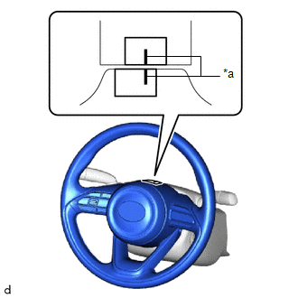
(3) Draw a line on the masking tape as shown in the illustration.
| (4) Turn the steering wheel assembly to the center position. HINT: Look at the upper surface of the steering wheel assembly, steering spoke and SRS airbag line to find the center position. |
|
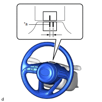
(5) Draw a new line on the masking tape on the steering wheel assembly as shown in the illustration.
(6) Measure the distance between the 2 lines on the masking tape on the steering wheel assembly.
(7) Convert the measured distance to steering angle.
HINT:
- Measured distance of 1 mm (0.0394 in.) = Steering angle of approximately 1 degree.
- Make a note of the steering angle.
(b) Adjust the steering angle.
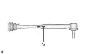
| (1) Draw a line on the RH and LH tie rod end sub-assemblies and rack end sub-assemblies where it can be easily seen. |
|
| (2) Remove the RH and LH steering rack boot clips from the steering rack boots. |
|
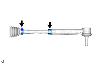
(3) Loosen the RH and LH lock nuts.
(4) Turn the RH and LH rack ends by the same amount (but in different directions) according to the steering angle.
HINT:
One 360 degree turn of the rack ends (1.0 mm (0.0394 in.)) horizontal movement equals 12 degrees of steering angle.
(5) Tighten the RH and LH lock nuts to the specified torque.
Click here

(6) Install the RH and LH steering rack boot clips.
(7) Perform calibration of torque sensor zero point.
Click here

 Installation
INSTALLATION PROCEDURE 1. INSTALL STEERING PAD SWITCH ASSEMBLY (a) Engage the 6 pins to install the steering pad switch assembly. (b) Connect the steering pad switch connector to the spiral cable sub-assembly...

Other information:
Toyota Yaris XP210 (2020-2026) Reapir and Service Manual: Data List / Active Test
DATA LIST / ACTIVE TEST DATA LIST NOTICE: In the table below, the values listed under "Normal Condition" are reference values. Do not depend solely on these reference values when deciding whether a part is faulty or not. HINT: Using the GTS to read the Data List allows the values or states of switches, sensors, actuators and other items to be read without removing any parts...
Toyota Yaris XP210 (2020-2026) Reapir and Service Manual: Fuel Sender Circuit Open (B150013,B150113)
DESCRIPTION The fuel sender gauge assembly is connected to the combination meter assembly via direct line. If there is an open or short in the direct line, the combination meter assembly stores DTC B150013. The fuel sender gauge assembly and No. 2 fuel sender gauge assembly are connected to the combination meter assembly via direct line...
Categories
- Manuals Home
- Toyota Yaris Owners Manual
- Toyota Yaris Service Manual
- G16e-gts (engine Mechanical)
- Immobilizer System
- Headlights
- New on site
- Most important about car
Break-In Period
No special break-in is necessary, but a few precautions in the first 600 miles (1,000 km) may add to the performance, economy, and life of the vehicle.
Do not race the engine. Do not maintain one constant speed, either slow or fast, for a long period of time. Do not drive constantly at full-throttle or high engine rpm for extended periods of time. Avoid unnecessary hard stops. Avoid full-throttle starts.