Toyota Yaris: Meter / Gauge System / Steering Pad Switch Circuit
DESCRIPTION
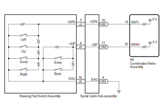
The combination meter assembly and steering pad switch assembly are connected via direct line. The multi-information display in the combination meter assembly are operated using the switches of the steering pad switch assembly.
WIRING DIAGRAM
CAUTION / NOTICE / HINT
NOTICE:
When replacing the combination meter assembly, always replace it with a new one. If a combination meter assembly which was installed to another vehicle is used, the information stored in it will not match the information from the vehicle and a DTC may be stored.
PROCEDURE
| 1. | INSPECT STEERING PAD SWITCH ASSEMBLY |
Click here

| NG |
 | REPLACE STEERING PAD SWITCH ASSEMBLY |
|

| 2. | INSPECT SPIRAL CABLE SUB-ASSEMBLY |
Click here

| NG |
 | REPLACE SPIRAL CABLE SUB-ASSEMBLY |
|

| 3. | CHECK HARNESS AND CONNECTOR (SPIRAL CABLE SUB-ASSEMBLY - COMBINATION METER ASSEMBLY) |
(a) Disconnect the H60 spiral cable sub-assembly connector.
(b) Disconnect the H6 combination meter assembly connector.
(c) Measure the resistance according to the value(s) in the table below.
Standard Resistance:
| Tester Connection | Condition | Specified Condition |
|---|---|---|
| H60-10 (+DP2) - H6-15 (MSTI) | Always | Below 1 Ω |
| H60-11 (+DP) -H6-32 (MSM+) | Always | Below 1 Ω |
| H60-4(EAU) - Body ground | Always | Below 1 Ω |
| H60-10 (+DP2) or H6-15 (MSTI) - Body ground | Always | 10 kΩ or higher |
| H60-11 (+DP) or H6-32 (MSM+) - Body ground | Always | 10 kΩ or higher |
| OK |
 | REPLACE COMBINATION METER ASSEMBLY |
| NG |
 | REPAIR OR REPLACE HARNESS OR CONNECTOR |
 Meter Illumination does not Dim at Night
DESCRIPTION In this circuit, the combination meter assembly receives auto dimmer signals from the main body ECU (multiplex network body ECU) via CAN communication...
 Speed Signal Circuit
DESCRIPTION HINT: This circuit is used for the systems connected to terminal +S. This signal is not used for combination meter assembly operation. Combination meter assembly components such as the speedometer operate using data received via CAN communication...
Other information:
Toyota Yaris XP210 (2020-2026) Reapir and Service Manual: Dtc Check / Clear
DTC CHECK / CLEAR HINT: DTCs, which are stored in the engine stop and start ECU, can be displayed on the GTS. The GTS can display confirmed and pending DTCs. Some DTCs are not stored if the engine stop and start ECU does not detect the same malfunction again during a second consecutive driving cycle...
Toyota Yaris XP210 (2020-2026) Reapir and Service Manual: Installation
INSTALLATION PROCEDURE 1. INSTALL AUTOMATIC LIGHT CONTROL SENSOR (a) Engage the claws to install the automatic light control sensor. 2. INSTALL INSTRUMENT MAIN PANEL Click here 3. INSTALL FRONT PILLAR GARNISH LH Click here 4. INSTALL FRONT PILLAR GARNISH RH HINT: Use the same procedure as for the LH side...
Categories
- Manuals Home
- Toyota Yaris Owners Manual
- Toyota Yaris Service Manual
- Opening and Closing the Liftgate/Trunk Lid
- Headlights
- Battery Monitor Module General Electrical Failure (P058A01)
- New on site
- Most important about car
Refueling
Before refueling, close all the doors, windows, and the liftgate/trunk lid, and switch the ignition OFF.
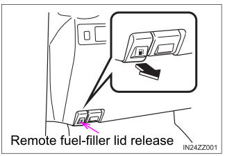
To open the fuel-filler lid, pull the remote fuel-filler lid release.