Toyota Yaris: Meter / Gauge System / Speed Signal Circuit
DESCRIPTION
HINT:
This circuit is used for the systems connected to terminal +S. This signal is not used for combination meter assembly operation. Combination meter assembly components such as the speedometer operate using data received via CAN communication. In addition, for some systems, vehicle speed information may be received via CAN communication.
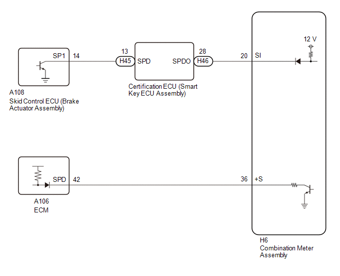
The combination meter assembly receives the vehicle speed signal from this circuit. The wheel speed sensors produce an output that varies according to the vehicle speed. The wheel speed sensor output is received by the skid control ECU (brake actuator assembly) which uses this information to create the vehicle speed signal. The vehicle speed signal is output from the skid control ECU (brake actuator assembly) to the certification ECU (smart key ECU assembly) and then to the combination meter assembly. To create this signal, 12 V is output from terminal SI of the combination meter assembly to the certification ECU (smart key ECU assembly). The pulse signal is created by switching the transistor in the certification ECU (smart key ECU assembly) on and off, making the voltage on the wire drop to 0 V. A similar system is used for the output of this signal from the combination meter assembly via terminal +S. A voltage of 12 V or 5 V is applied to terminal +S from each ECU or relay that is connected to this terminal. The transistor in the combination meter assembly is controlled by the signal from the certification ECU (smart key ECU assembly). When this transistor is turned on, this transistor makes the voltage supplied by the various ECUs (via their respective internal resistors) drop to 0 V. Each ECU connected to terminal +S of the combination meter assembly controls its respective system based on this pulse signal.
WIRING DIAGRAM
CAUTION / NOTICE / HINT
NOTICE:
- When replacing the combination meter assembly, always replace it with a new one. If a combination meter assembly which was installed to another vehicle is used, the information stored in it will not match the information from the vehicle and a DTC may be stored.
-
Before replacing the certification ECU (smart key ECU assembly), refer to Registration.
Click here

PROCEDURE
| 1. | CHECK FOR DTC (ENTRY AND START SYSTEM (FOR START FUNCTION)) |
(a) Check for entry and start system (for start function) DTCs.
Body Electrical > Power Source Control > Trouble Codes| Result | Proceed to |
|---|---|
| DTCs are not output | A |
| DTCs are output | B |
| B |
 | GO TO ENTRY AND START SYSTEM (FOR START FUNCTION) |
|

| 2. | CHECK COMBINATION METER ASSEMBLY (INPUT VOLTAGE) |
(a) Disconnect the H6 combination meter assembly connector.
(b) Measure the voltage according to the value(s) in the table below.
Standard Voltage:
| Tester Connection | Switch Condition | Specified Condition |
|---|---|---|
| H6-36 (+S) - Body ground | Ignition switch ON | 11 to 14 V |
| NG |
 | GO TO STEP 6 |
|

| 3. | CHECK COMBINATION METER ASSEMBLY (OUTPUT VOLTAGE) |
(a) Disconnect the H46 certification ECU (smart key ECU assembly) connector.
(b) Measure the voltage according to the value(s) in the table below.
Standard Voltage:
| Tester Connection | Switch Condition | Specified Condition |
|---|---|---|
| H46-28 (SPDO) - Body ground | Ignition switch ON | 11 to 14 V |
| NG |
 | GO TO STEP 5 |
|

| 4. | CHECK COMBINATION METER ASSEMBLY (INPUT WAVEFORM) |
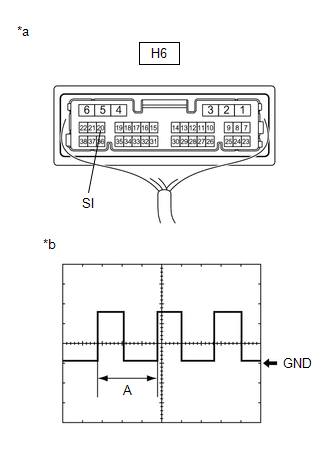
| *a | Component with harness connected (Combination Meter Assembly) |
| *b | Waveform |
(a) Connect the H46 certification ECU (smart key ECU assembly) connector.
(b) Remove the combination meter assembly with the connector(s) still connected.
Click here

(c) Check the signal waveform according to the condition(s) in the table below.
| Item | Condition |
|---|---|
| Tester connection | H6-20 (SI) - Body ground |
| Tool setting | 5 V/DIV., 20 ms./DIV. |
| Condition | Ignition switch ON, wheel being rotated |
OK:
The waveform is similar to that shown in the illustration.
HINT:
When the system is functioning normally, one wheel revolution generates 4 pulses. As the vehicle speed increases, the width indicated by (A) in the illustration narrows.
| OK |
 | REPLACE COMBINATION METER ASSEMBLY |
| NG |
 | REPLACE CERTIFICATION ECU (SMART KEY ECU ASSEMBLY) |
| 5. | CHECK HARNESS AND CONNECTOR (CERTIFICATION ECU (SMART KEY ECU ASSEMBLY) - COMBINATION METER ASSEMBLY) |
(a) Disconnect the H6 combination meter assembly connector.
(b) Measure the resistance according to the value(s) in the table below.
Standard Resistance:
| Tester Connection | Condition | Specified Condition |
|---|---|---|
| H46-28 (SPDO) - H6-20 (SI) | Always | Below 1 Ω |
| H46-28 (SPDO) or H6-20 (SI) - Body ground | Always | 10 kΩ or higher |
| OK |
 | REPLACE COMBINATION METER ASSEMBLY |
| NG |
 | REPAIR OR REPLACE HARNESS OR CONNECTOR |
| 6. | CHECK HARNESS AND CONNECTOR (EACH ECU - COMBINATION METER ASSEMBLY) |
(a) Disconnect the H6 combination meter assembly connector.
(b) Disconnect the A106 ECM connector.
(c) Measure the resistance according to the value(s) in the table below.
Standard Resistance:
| Tester Connection | Condition | Specified Condition |
|---|---|---|
| H6-36 (+S) - A106-42 (SPD) | Always | Below 1 Ω |
| H6-36 (+S) - Body ground | Always | 10 kΩ or higher |
| NG |
 | REPAIR OR REPLACE HARNESS OR CONNECTOR |
|

| 7. | CHECK ECM |
(a) Disconnect the H6 combination meter assembly connector.
(b) Disconnect the A106 ECM connector.
(c) Measure the voltage according to the value(s) in the table below.
Standard Voltage:
| Tester Connection | Switch Condition | Specified Condition |
|---|---|---|
| H6-36 (+S) - Body ground | Ignition switch ON | 11 to 14 V |
HINT:
If the result is as specified, there may be a short circuit in the ECM.
| OK |
 | REPLACE ECM |
| NG |
 | REPLACE COMBINATION METER ASSEMBLY |
 Steering Pad Switch Circuit
DESCRIPTION The combination meter assembly and steering pad switch assembly are connected via direct line. The multi-information display in the combination meter assembly are operated using the switches of the steering pad switch assembly...
 Mirror (int)
..
Other information:
Toyota Yaris XP210 (2020-2026) Reapir and Service Manual: Starter Relay Signal Compare Failure (P061562)
DESCRIPTION When the STA signal detected by the ECM and by the engine stop and start ECU do not match, the engine stop and start ECU stores DTC P061562 and blinks the stop and start cancel indicator. DTC No. Detection Item DTC Detection Condition Trouble Area Warning Indicate Memory Note P061562 Starter Relay Signal Compare Failure Both of the following conditions are met for 2 seconds or more (1 trip detection logic): Normal communication with the ECM...
Toyota Yaris XP210 (2020-2026) Reapir and Service Manual: Front Disc Brake Pad
C..
Categories
- Manuals Home
- Toyota Yaris Owners Manual
- Toyota Yaris Service Manual
- Removal
- Key Battery Replacement
- Adjustment
- New on site
- Most important about car
Key Suspend Function
If a key is left in the vehicle, the functions of the key left in the vehicle are temporarily suspended to prevent theft of the vehicle.
To restore the functions, press the unlock button on the functions-suspended key in the vehicle.