Toyota Yaris: Vehicle Stability Control System / Steering Angle Sensor Supply Voltage Circuit Circuit Short to Ground or Open (C14FE14)
DESCRIPTION
This DTC is stored when the skid control ECU (brake actuator assembly) receives a power supply malfunction signal from the steering sensor.
| DTC No. | Detection Item | DTC Detection Condition | Trouble Area | DTC Output from |
|---|---|---|---|---|
| C14FE14 | Steering Angle Sensor Supply Voltage Circuit Circuit Short to Ground or Open | When the +BS terminal voltage is from 9.5 to 17.4 V, a steering sensor power supply malfunction signal is received from the steering sensor. |
| Brake |
WIRING DIAGRAM
Refer to DTC C05262A.
Click here

CAUTION / NOTICE / HINT
NOTICE:
Inspect the fuses for circuits related to this system before performing the following procedure.
PROCEDURE
| 1. | CLEAR DTC |
(a) Clear the DTCs.
Chassis > Brake > Clear DTCs(b) Turn the ignition switch off.
|

| 2. | RECONFIRM DTC |
(a) Based on the Freeze Frame Data and interview with the customer, attempt to reproduce the conditions when the malfunction occurred.
(b) Check if the same DTC is output.
Chassis > Brake > Trouble Codes| Result | Proceed to |
|---|---|
| DTC C14FE14 is not output. | A |
| DTC C14FE14 is output. | B |
| A |
 | USE SIMULATION METHOD TO CHECK |
|

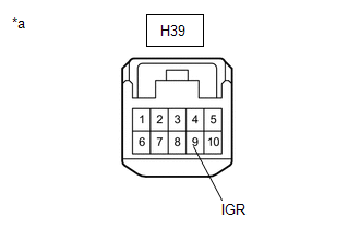
| 3. | CHECK HARNESS AND CONNECTOR (IGR TERMINAL) |
(a) Make sure that there is no looseness at the locking part and the connecting part of the connectors.
OK:
The connector is securely connected.
| (b) Disconnect the H39 steering sensor connector. |
|
(c) Check both the connector case and the terminals for deformation and corrosion.
OK:
No deformation or corrosion.
(d) Turn the ignition switch to ON.
(e) Measure the voltage according to the value(s) in the table below.
Standard Voltage:
| Tester Connection | Condition | Specified Condition |
|---|---|---|
| H39-9 (IGR) - Body ground | Ignition switch ON | 11 to 14 V |
| NG |
 | REPAIR OR REPLACE HARNESS OR CONNECTOR |
|

| 4. | CHECK HARNESS AND CONNECTOR (BAT TERMINAL) |
| (a) Turn the ignition switch off. |
|
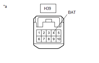
(b) Measure the voltage according to the value(s) in the table below.
Standard Voltage:
| Tester Connection | Condition | Specified Condition |
|---|---|---|
| H39-4 (BAT) - Body ground | Always | 11 to 14 V |
| NG |
 | REPAIR OR REPLACE HARNESS OR CONNECTOR |
|

| 5. | CHECK HARNESS AND CONNECTOR (ESS TERMINAL) |
(a) Measure the resistance according to the value(s) in the table below.
Standard Resistance:
| Tester Connection | Condition | Specified Condition |
|---|---|---|
| H39-6 (ESS) - Body ground | 1 minute or more after disconnecting the cable from the negative (-) auxiliary battery terminal | Below 1 Ω |
| OK |
 | REPLACE STEERING SENSOR |
| NG |
 | REPAIR OR REPLACE HARNESS OR CONNECTOR |
 Left Rear Wheel Speed Sensor Supply Voltage Circuit Short to Ground or Open (C14E614,C14E914)
DESCRIPTION Refer to DTC C050C1F. Click here
DTC No. Detection Item DTC Detection Condition Trouble Area DTC Output from C14E614 Left Rear Wheel Speed Sensor Supply Voltage Circuit Short to Ground or Open With the +BS terminal voltage 9...
 Brake Switch "A" Circuit Short to Ground (P057111)
DESCRIPTION The skid control ECU (brake actuator assembly) inputs the stop light signal and brake operation condition. When the brake pedal is depressed and the stop light switch signal is not input, this DTC is output...
Other information:
Toyota Yaris XP210 (2020-2025) Reapir and Service Manual: On-vehicle Inspection
ON-VEHICLE INSPECTION CAUTION / NOTICE / HINT CAUTION: To prevent injury due to contact with an operating V-ribbed belt or cooling fan, keep your hands and clothing away from the V-ribbed belt and cooling fan when working in the engine compartment with the engine running or the ignition switch ON...
Toyota Yaris XP210 (2020-2025) Reapir and Service Manual: Removal
REMOVAL CAUTION / NOTICE / HINT NOTICE: Wash the vehicle to prevent oil and other dirt from remaining on the roof panel, which is the adhesive surface of the roof outside cover. Do not use a detergent mixed with wax. When replacing the roof outside cover, it is necessary to apply clear coating to the roof panel surface to smooth the unevenness of the roof panel...
Categories
- Manuals Home
- Toyota Yaris Owners Manual
- Toyota Yaris Service Manual
- To Set Speed
- Removal
- Adjustment
- New on site
- Most important about car
Keys

To use the auxiliary key, press the knob and pull out the auxiliary key from the smart key.
