Toyota Yaris: Vehicle Stability Control System / Steering Angle Sensor Module Signal Stuck In Range (C05262A)
DESCRIPTION
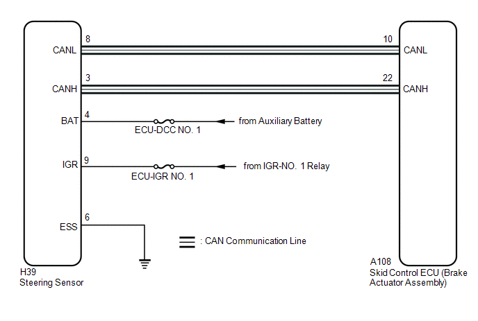
The skid control ECU (brake actuator assembly) receives signals from the steering sensor via CAN communication.
HINT:
When a malfunction occurs in the communication line to the steering sensor, U012687 is output.
If a DTC related to the CAN communication line is output, first troubleshoot the CAN communication line.
| DTC No. | Detection Item | DTC Detection Condition | Trouble Area | DTC Output from |
|---|---|---|---|---|
| C05262A | Steering Angle Sensor Module Signal Stuck In Range | Normal communication between the skid control ECU and the steering sensor and abnormal steering sensor zero point. |
| Brake |
WIRING DIAGRAM

CAUTION / NOTICE / HINT
NOTICE:
Inspect the fuses for circuits related to this system before performing the following procedure.
PROCEDURE
| 1. | RECONFIRM DTC (CAN COMMUNICATION SYSTEM) |
(a) Operate the GTS, and check for DTCs related to the CAN communication system.
Click here

| Result | Proceed to |
|---|---|
| Any CAN communication system relating DTCs are output | A |
| None of the above conditions are met | B |
| A |
 | INSPECT CAN COMMUNICATION SYSTEM |
|
| 2. | CLEAR DTC |
(a) Operate the GTS to clear the codes.
Chassis > Brake > Clear DTCs(b) Turn the ignition switch off.
|
| 3. | RECONFIRM DTC |
(a) Drive the vehicle at a speed of 35 km/h (22 mph) and turn the steering wheel to the right and left.
(b) Operate the GTS to read the DTCs.
Chassis > Brake > Trouble Codes(c) Check that no speed sensor or yaw rate sensor (airbag sensor assembly) DTCs are output.
HINT:
- If a speed sensor, or the yaw rate sensor (airbag sensor assembly) is malfunctioning, DTCs for the steering sensor may be stored even though the steering sensor is normal.
- If speed sensor and yaw rate sensor (airbag sensor assembly) DTCs are output simultaneously, repair these malfunctions and then inspect the steering sensor.
| Result | Proceed to |
|---|---|
| Only C05262A is output | A |
| Speed sensor and/or yaw rate sensor (airbag sensor assembly) DTCs are output. | B |
| B |
 | REPAIR CIRCUITS INDICATED BY OUTPUT DTCS |
|
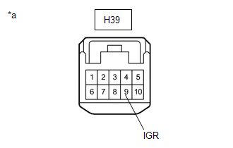
| 4. | CHECK HARNESS AND CONNECTOR (IGR TERMINAL) |
(a) Turn the ignition switch off.
(b) Make sure that there is no looseness at the locking part and the connecting part of the connectors.
OK:
The connector is securely connected.
| (c) Disconnect the H39 steering sensor connector. |
|
(d) Check both the connector case and the terminals for deformation and corrosion.
OK:
No deformation or corrosion.
(e) Turn the ignition switch to ON.
(f) Measure the voltage according to the value(s) in the table below.
Standard Voltage:
| Tester Connection | Condition | Specified Condition |
|---|---|---|
| H39-9 (IGR) - Body ground | Ignition switch ON | 11 to 14 V |
| NG |
 | REPAIR OR REPLACE HARNESS OR CONNECTOR |
|
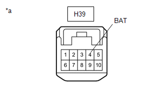
| 5. | CHECK HARNESS AND CONNECTOR (BAT TERMINAL) |
| (a) Turn the ignition switch off. |
|
(b) Measure the voltage according to the value(s) in the table below.
Standard Voltage:
| Tester Connection | Condition | Specified Condition |
|---|---|---|
| H39-4 (BAT) - Body ground | Always | 11 to 14 V |
| NG |
 | REPAIR OR REPLACE HARNESS OR CONNECTOR |
|
| 6. | CHECK HARNESS AND CONNECTOR (ESS TERMINAL) |
(a) Measure the resistance according to the value(s) in the table below.
Standard Resistance:
| Tester Connection | Condition | Specified Condition |
|---|---|---|
| H39-6 (ESS) - Body ground | 1 minute or more after disconnecting the cable from the negative (-) auxiliary battery terminal | Below 1 Ω |
| OK |
 | REPLACE STEERING SENSOR |
| NG |
 | REPAIR OR REPLACE HARNESS OR CONNECTOR |
 Right Rear Wheel Speed Sensor Signal Stuck Low (C051223)
DESCRIPTION Refer to DTC C05121F. Click here
DTC No. Detection Item DTC Detection Condition Trouble Area DTC Output from C051223 Right Rear Wheel Speed Sensor Signal Stuck Low Any of the following is detected:
When the +BS terminal voltage is 17...
 Steering Angle Sensor Module Component Internal Failure (C052696)
DESCRIPTION The skid control ECU (brake actuator assembly) outputs this DTC when it receives an internal malfunction signal from the steering sensor. DTC No...
Other information:
Toyota Yaris XP210 (2020-2026) Reapir and Service Manual: Engine Coolant Temperature Receiver Gauge Malfunction
DESCRIPTION In this circuit, the combination meter assembly receives engine coolant temperature signals from the ECM via CAN communication. The combination meter assembly displays an engine coolant temperature warning based on the data received from the ECM...
Toyota Yaris XP210 (2020-2026) Reapir and Service Manual: Installation
INSTALLATION CAUTION / NOTICE / HINT NOTICE: After performing the ECU configuration procedure and update ECU security key procedure, make sure to perform the initialization procedure for when the cable has been disconnected and reconnected to the negative (-) auxiliary battery terminal...
Categories
- Manuals Home
- Toyota Yaris Owners Manual
- Toyota Yaris Service Manual
- Adjustment
- Brake System Control Module "A" System Voltage System Voltage Low (C137BA2)
- Fuse Panel Description
- New on site
- Most important about car
Key Suspend Function
If a key is left in the vehicle, the functions of the key left in the vehicle are temporarily suspended to prevent theft of the vehicle.
To restore the functions, press the unlock button on the functions-suspended key in the vehicle.


