Toyota Yaris: Lighting (int) / Room Light Bulb
Replacement
REPLACEMENT
PROCEDURE
1. REMOVE NO. 1 ROOM LIGHT BULB
(a) Using a screwdriver with its tip wrapped in protective tape, disengage the claws to remove the No. 1 room light lens as shown in the illustration.
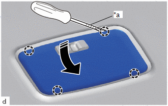
| *a | Protective Tape |
 | Remove in this Direction |
(b) Remove the No. 1 room light bulb as shown in the illustration.
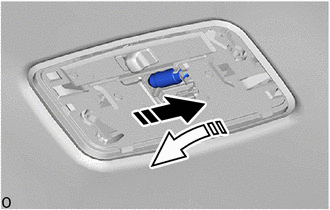
 | Remove in this Direction (1) |
 | Remove in this Direction (2) |
2. INSTALL NO. 1 ROOM LIGHT BULB
(a) Install the No. 1 room light bulb as shown in the illustration.
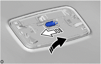
 | Install in this Direction (1) |
 | Install in this Direction (2) |
(b) Engage the claws to install the No. 1 room light lens as shown in the illustration.
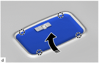
 | Install in this Direction |
 Room Light
ComponentsCOMPONENTS ILLUSTRATION
*1 NO. 1 ROOM LIGHT ASSEMBLY *2 NO. 1 ROOM LIGHT BULB *3 NO. 1 ROOM LIGHT LENS *4 NO. 1 ROOM LIGHT HOUSING RemovalREMOVAL PROCEDURE 1...

Other information:
Toyota Yaris XP210 (2020-2026) Reapir and Service Manual: Removal
REMOVAL CAUTION / NOTICE / HINT The necessary procedures (adjustment, calibration, initialization or registration) that must be performed after parts are removed and installed, or replaced during canister (fuel suction plate sub-assembly) removal/installation are shown below...
Toyota Yaris XP210 (2020-2026) Owner's Manual: Key Battery Replacement
If the buttons on the smart key are inoperable and the operation indicator light does not flash, the battery may be dead. Replace with a new battery before the smart key becomes unusable. The following conditions indicate that the battery power is low: The KEY indicator light (green) flashes in the combination meter for about 30 seconds after the engine is switched OFF...
Categories
- Manuals Home
- Toyota Yaris Owners Manual
- Toyota Yaris Service Manual
- Diagnostic Trouble Code Chart
- Engine & Hybrid System
- Brake System Control Module "A" System Voltage System Voltage Low (C137BA2)
- New on site
- Most important about car
Supplemental Restraint System (SRS) Precautions
The front and side supplemental restraint systems (SRS) include different types of air bags. Please verify the different types of air bags which are equipped on your vehicle by locating the “SRS AIRBAG” location indicators. These indicators are visible in the area where the air bags are installed.
The air bags are installed in the following locations:
The steering wheel hub (driver air bag) The front passenger dashboard (front passenger air bag) The outboard sides of the front seatbacks (side air bags) The front and rear window pillars, and the roof edge along both sides (curtain air bags)